Zoom lens system and imaging optical device employing the same
a zoom lens and optical device technology, applied in the field of zoom lens system and imaging optical device, can solve the problems of large size and weight reduction, large number of lens elements in the lens system, and large weight of blur compensation lens units, etc., to achieve simple construction, reduce the number of lens elements, and reduce the effect of size and weigh
- Summary
- Abstract
- Description
- Claims
- Application Information
AI Technical Summary
Benefits of technology
Problems solved by technology
Method used
Image

Examples
embodiment 1
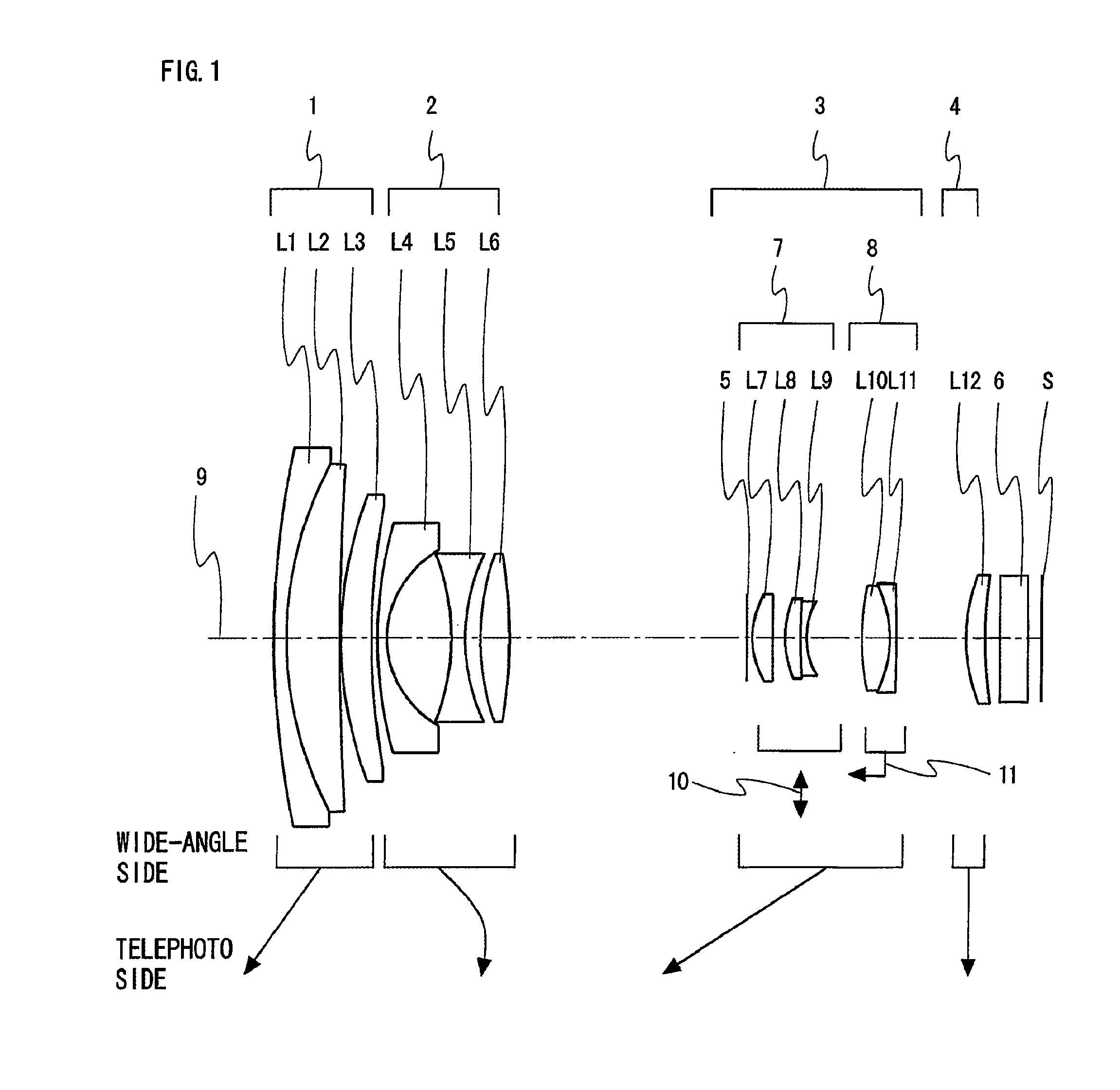
[0084]FIG. 1 is an arrangement diagram showing a lens configuration of a zoom lens system according to Embodiment 1 at a wide-angle limit in a normal state.
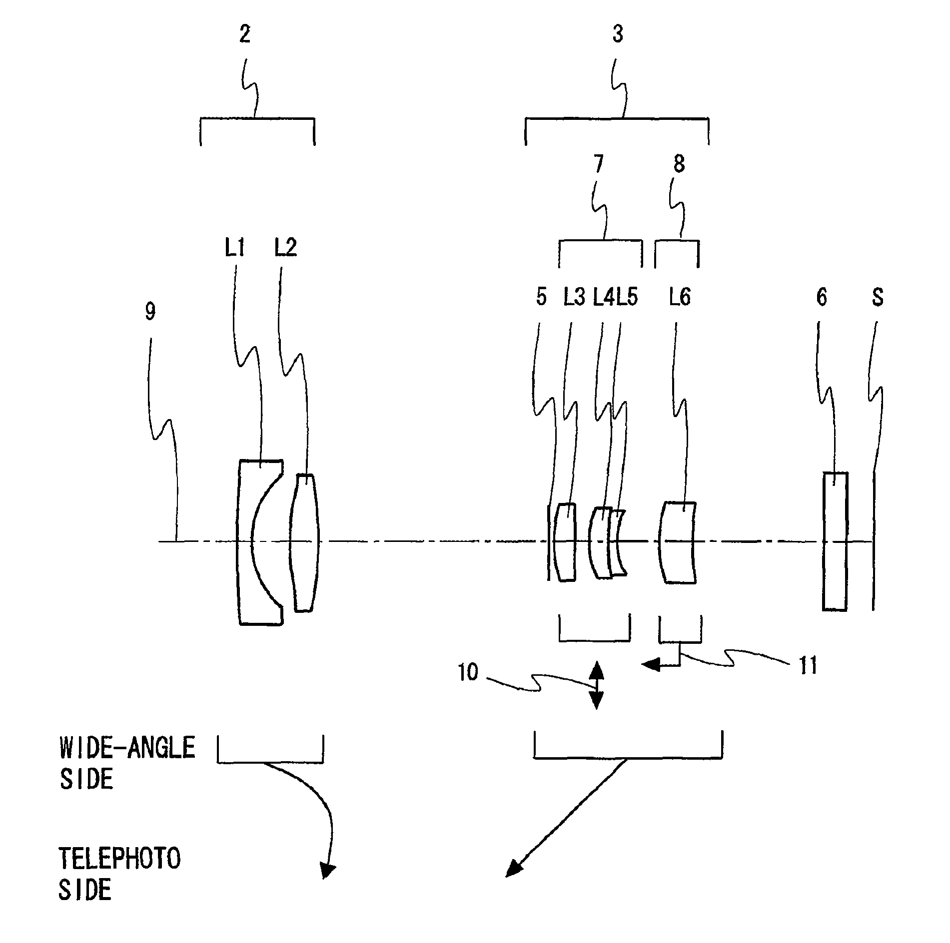
[0085]As shown in FIG. 1, the zoom lens system according to Embodiment 1, in order from the object side (left-hand side in FIG. 1) to the image side (image surface S side), comprises: a front additional lens unit 1 having positive optical power; a front lens unit 2 having negative optical power; a rear lens unit 3 having positive optical power; and a rear additional lens unit 4 having positive optical power. Then, at least the rear lens unit 3 is moved in the direction of an optical axis 9 (the “optical axis” indicates the “optical axis 9”, hereinafter), so that magnification change is performed. On the most object side of the rear lens unit 3, an aperture diaphragm 5 is arranged for restricting the optical path. Further, near the image surface S located between the rear additional lens unit 4 and the image surface S, an optical ...
embodiment 2
[0108]FIG. 3 is an arrangement diagram showing a lens configuration of a zoom lens system according to Embodiment 2 at a wide-angle limit in a normal state. The zoom lens system according to Embodiment 2, in order from the object side (left-hand side in FIG. 3) to the image side, comprises: a front additional lens unit 1 having positive optical power; a front lens unit 2 having negative optical power; a rear lens unit 3 having positive optical power; and a rear additional lens unit 4 having positive optical power. Its basic configuration and the like are the same as those of the zoom lens system according to Embodiment 1. Thus, specific configurations of the individual lens units are solely described below in details.
[0109]As shown in FIG. 3, the front additional lens unit 1, in order from the object side to the image side, comprises two lens elements consisting of: a negative meniscus lens element L1 with the convex surface facing the object side; and a positive meniscus lens eleme...
embodiment 3
[0115]FIG. 4 is an arrangement diagram showing a lens configuration of a zoom lens system according to Embodiment 3 at a wide-angle limit in a normal state. The zoom lens system according to Embodiment 3, in order from the object side (left-hand side in FIG. 4) to the image side, comprises: a front additional lens unit 1 having positive optical power; a front lens unit 2 having negative optical power; a rear lens unit 3 having positive optical power; and a rear additional lens unit 4 having positive optical power. Its basic configuration and the like are the same as those of the zoom lens system according to Embodiment 1. Thus, specific configurations of the individual lens units are solely described below in details.
[0116]As shown in FIG. 4, the front additional lens unit 1 is constructed only from a positive meniscus lens element L1 with the convex surface facing the object side. Thus, size and weight reduction is achieved in the lens system.
[0117]The front lens unit 2, in order f...
PUM
 Abstract
Description
Claims
Application Information
 - R&D
- Intellectual Property
- Life Sciences
- Materials
- Tech Scout
- Unparalleled Data Quality
- Higher Quality Content
- 60% Fewer Hallucinations
Browse by: Latest US Patents, China's latest patents, Technical Efficacy Thesaurus, Application Domain, Technology Topic, Popular Technical Reports.
© 2025 PatSnap. All rights reserved.Legal|Privacy policy|Modern Slavery Act Transparency Statement|Sitemap|About US| Contact US: help@patsnap.com