
Handheld balloon launching apparatus

Inactive Publication Date: 2010-06-01
COLEMAN SEAN
View PDF5 Cites 6 Cited by
  • Summary
  • Abstract
  • Description
  • Claims
  • Application Information

AI Technical Summary

Benefits of technology

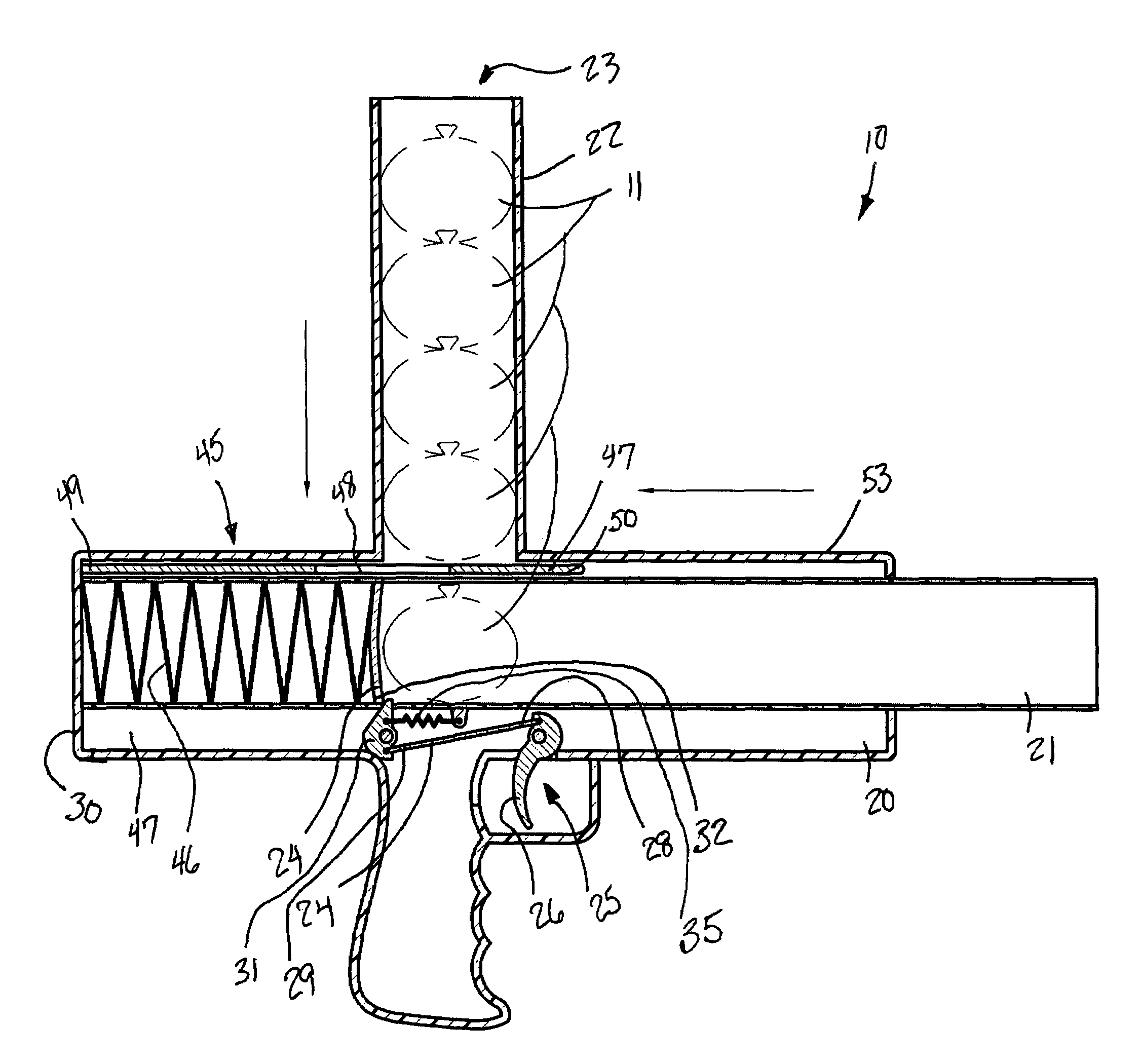
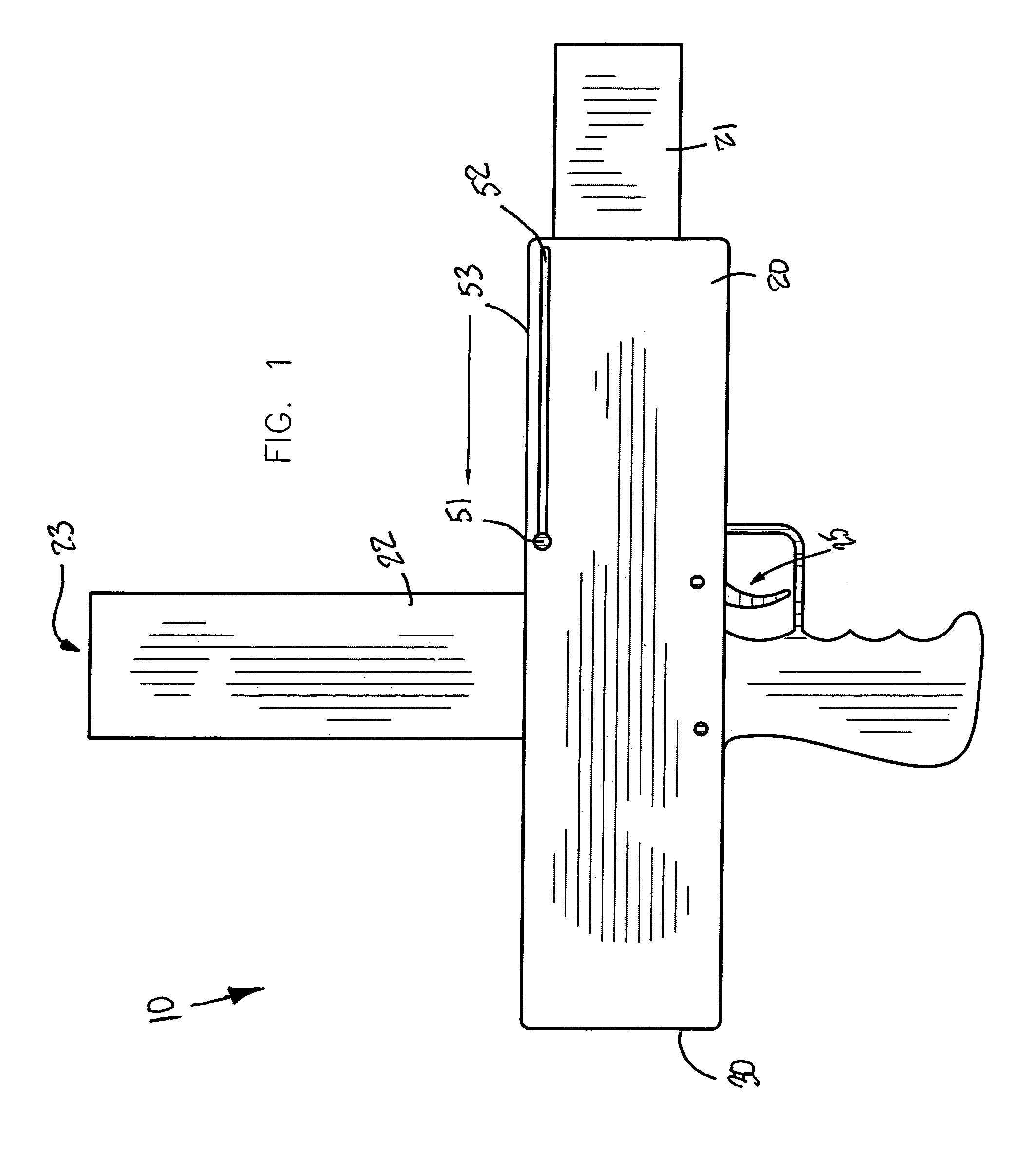
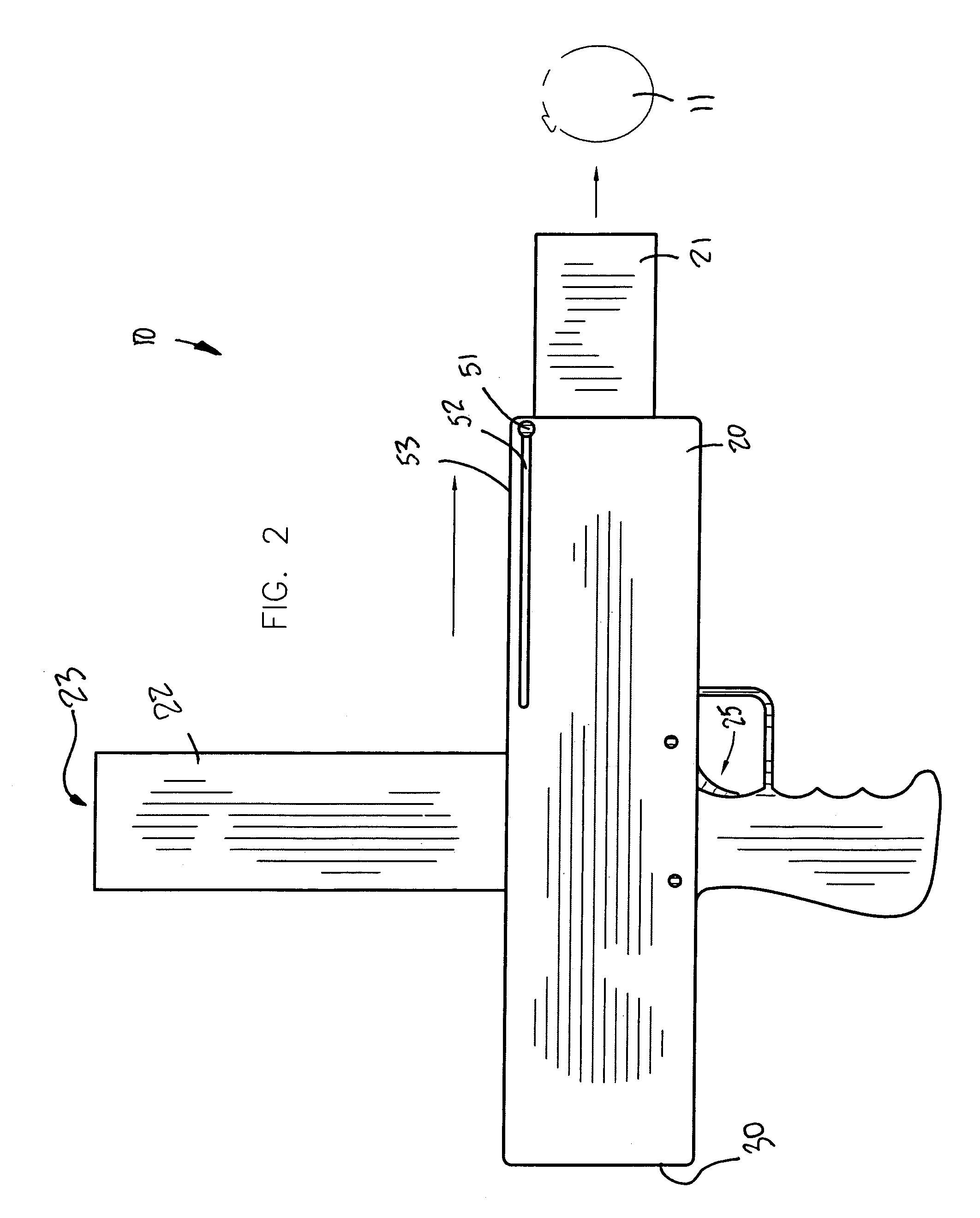
[0012]The apparatus includes a tubular housing that has an axially offset chamber formed therein. Such a housing further has a vertically registered intake port effectively defining a linear passageway in which the filled water balloons are vertically stacked. A launching plate has a curvilinear shape conforming to an outer contour of a water balloon, and is selectively adaptable along a longitudinal length of the chamber. A trigger mechanism conveniently activates the launching plate between a compressed position and a fully extended position.
[0013]The triggering mechanism includes a primary trigger pivotally connected to the housing and partially exposed exterior thereof. A rectilinear rod has a distal end directly anchored to the primary trigger and has a proximal end horizontally offset and sloped downwardly towards a proximal end of the housing. An auxiliary trigger is pivotally connected to the housing and directly mated with the proximal end of the rod. Such an auxiliary trigger is directly and releasably engaged with a bottom portion of the launching plate while the launching mechanism (herein described below) is advantageously maintained at the compressed position. The primary trigger rotates along a first arcuate path when depressed by a user to thereby effectively cause the rod to linearly displace distally and thereby rotate the auxiliary trigger along a second arcuate path effectively defined opposite to the first arcuate path.
[0015]The apparatus further includes a mechanism for returning the launching plate to the compressed position while simultaneously depositing a lowest one of the water balloons directly in front of and abutted distally to the launching plate such that an adjacent one of the water balloons seated on top of the lowest water balloon is advantageously prohibited from entering the chamber. Such a returning mechanism includes a deformably resilient spring member that has a diameter substantially equal to a diameter of the chamber and is advantageously anchored to a proximal end of the chamber. Such a spring member is conveniently extendable along the longitudinal length of the chamber. The launching plate effectively maintains a static relationship with the returning mechanism during launching operations, and the returning mechanism is independently operable from the triggering mechanism.
[0016]The launching plate return mechanism further includes a segmented linear return plate that has an opening formed therein that effectively defines the plate into proximal and distal segments. Such a distal segment has a lever monolithically formed therewith that terminates exterior of the housing. The housing includes a linear slot formed adjacent to a top edge thereof. The return plate is directly and monolithically coupled to the launching plate such that the user can manually position the return plate proximally along the chamber and thereby advantageously return the launching plate to the compressed position. The opening of the return plate becomes vertically aligned with the passageway for effectively allowing the lowest one of the water balloons to advantageously fall through the opening and conveniently rest against the launching plate.

Problems solved by technology

Unfortunately, such an apparatus is complicated and time consuming to set up, and also requires a large amount of free space in which to set up the apparatus.
Unfortunately, such an apparatus is complicated to use and not easily transportable.
Such an apparatus is difficult for youths and those with limited dexterity to easily use.

Method used


Image

  • Handheld balloon launching apparatus
  • Handheld balloon launching apparatus
  • Handheld balloon launching apparatus

Examples


Embodiment Construction

[0025]The present invention will now be described more fully hereinafter with reference to the accompanying drawings, in which a preferred embodiment of the invention is shown. This invention may, however, be embodied in many different forms and should not be construed as limited to the embodiment set forth herein. Rather, this embodiment is provided so that this application will be thorough and complete, and will fully convey the true scope of the invention to those skilled in the art. Like numbers refer to like elements throughout the figures.

[0026]The apparatus of this invention is referred to generally in FIGS. 1-5 by the reference numeral 10 and is intended to provide a handheld balloon launching apparatus. It should be understood that the apparatus 10 may be used to launch many different types of objects and should not be limited in use to launching only those types of objects described herein.

[0027]Referring initially to FIGS. 1, 2, 3, 4 and 5, the apparatus 10 includes a tub...


PUM


Abstract

A handheld balloon launcher includes a housing with an axially offset chamber formed therein. A vertically registered intake port defines a linear passageway in which filled water balloons are stacked. A launching plate is selectively adaptable along a longitudinal length of the chamber. A trigger mechanism activates the launching plate between a compressed and an extended position. A mechanism returns the launching plate to the compressed position while simultaneously depositing one of the water balloons in front of the launching plate. The returning mechanism includes a spring member with a diameter equal to a diameter of the chamber and anchored to a proximal end thereof, and extendable along the longitudinal length of the chamber. The launching plate maintains a static relationship with the returning mechanism, and the returning mechanism is independently operable from the triggering mechanism.

Description

CROSS REFERENCE TO RELATED APPLICATIONS[0001]This application claims the benefit of U.S. Provisional Application No. 60 / 734,533, filed Nov. 9, 2005.STATEMENT REGARDING FEDERALLY SPONSORED RESEARCH OR DEVELOPMENT[0002]Not Applicable.REFERENCE TO A MICROFICHE APPENDIX[0003]Not Applicable.BACKGROUND OF THE INVENTION[0004]1. Technical Field[0005]This invention relates to launching apparatuses and, more particularly, to a handheld balloon launching apparatus for assisting a user to propel a plurality of filled water balloons along a predetermined trajectory.[0006]2. Prior Art[0007]Toy balloons are typically made from latex rubber or similar expandable material, and are usually filled with air or other gas for use as a toy or decoration. Alternatively, many users desire to fill their balloons with water or other liquid so they may use them as “water balloons”, which can then be thrown to intentionally break or “explode” upon impact with a target as such as the ground, or an unfortunate pl...

Claims


Application Information

Patent Timeline
IPC IPC(8): F41B7/08F41B7/00
CPCF41B7/08
Inventor COLEMAN, SEAN
Owner COLEMAN SEAN
Learn More