Wireless power transfer system

a power transfer system and wireless technology, applied in the direction of charging stations, electric vehicle charging technology, transportation and packaging, etc., can solve the problems of slow adoption of inductive charging technology, difficulty in user anticipatory behavior, and inability to detect inductive charging systems, etc., to achieve efficient power transfer

Inactive Publication Date: 2010-06-01
VISTEON GLOBAL TECH INC
View PDF15 Cites 55 Cited by
  • Summary
  • Abstract
  • Description
  • Claims
  • Application Information

AI Technical Summary

Benefits of technology

[0010]The present invention allows an electronic device having a secondary coil to be positioned proximate to the primary induction coil of the wireless power transfer system for efficient power transfer without exact positioning of the electronic device relative to the primary coil.

Problems solved by technology

It is difficult for users to anticipate when they will be near a power source for a sufficient time period to charge the battery within the device.
One resolution to the cumbersome use of such charging cords has been the introduction of electromagnetic induction technology; however manufacturers of vehicles have been slow to adopt such technology.
Due to the difficulty in arranging specific interfaces within a vehicle, the inventors are not aware of any inductive charging systems currently being used in production vehicles for powering or charging a device.
Wireless power transfer systems eliminate the need to have open electrical contacts; however, the electromagnetic fields generated by such systems are relatively small.

Method used


Image

  • Wireless power transfer system
  • Wireless power transfer system
  • Wireless power transfer system

Examples


Embodiment Construction

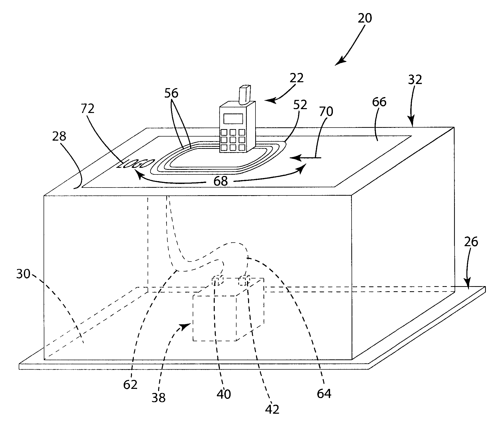
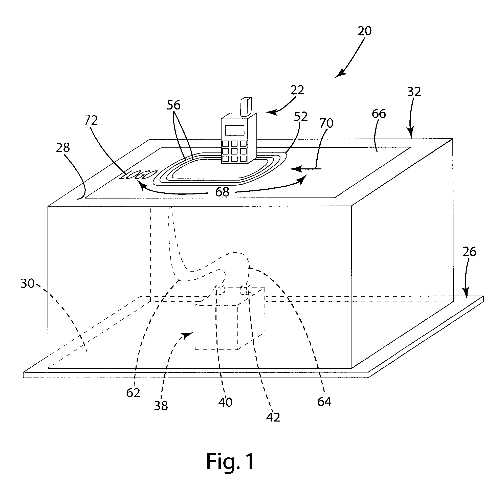
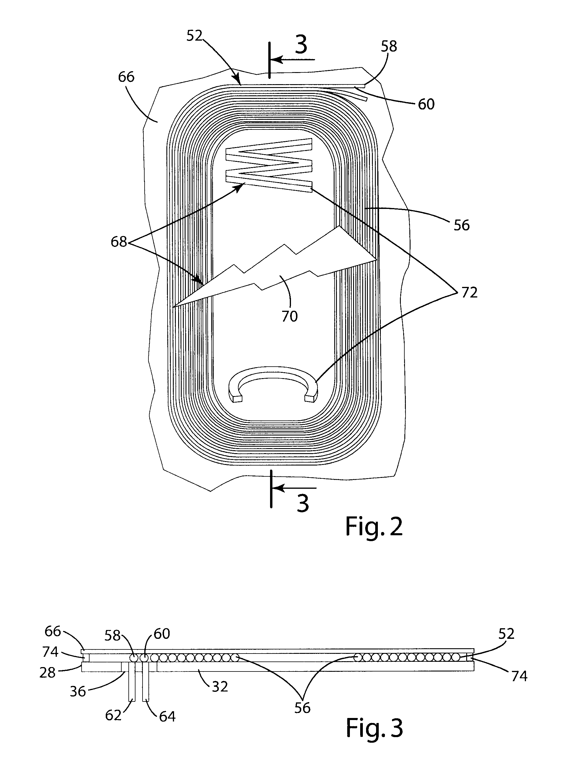
[0016]Referring to the Figures, wherein like numerals indicate corresponding parts throughout the several views, a wireless power transfer system 20 is generally shown for charging an electronic device 22. The electronic device 22 includes a secondary coil 24 for receiving power from the power transfer system 20 and is shown as a cell phone, however, it should be appreciated that the present invention is designed for use with many other electronic devices 22 including, but not limited to, personal data assistants and portable music players.

[0017]The wireless power transfer system 20 generally comprises a primary controller 38, a primary coil 52, a protective shield 66, and a support structure 26. The support structure 26 is generally indicated in FIG. 1 and has a class A surface 28. The class A surface 28 can be any surface which is visible or easily accessible to the user. The support structure may further include a class B surface, which is any surface not readily visible or acces...


PUM


Abstract

A wireless power transfer system 20 for charging an electronic device 22 having a secondary coil 24 includes a primary controller 38 disposed on a class B surface 30 of a vehicle. A primary coil 52 is electrically connected to the primary controller 38. The primary coil 52 is disposed remotely from the primary controller 38 on a class A surface 28 of the vehicle. A protective shield 66 is disposed on the primary coil 52 to secure the primary coil 52 to the class A surface 28 and indicia 68 indicating an alignment of the secondary coil 24 of the electronic device 22 is disposed on the protective shield 66.

Description

BACKGROUND OF THE INVENTION[0001]1. Field of the Invention[0002]The subject invention relates to a wireless power transfer system for powering or charging an electronic device or a battery, and more specifically, to a wireless power transfer system for a vehicle having a controller and a remote primary coil for inductively charging a secondary coil in an electronic device.[0003]2. Description of the Prior Art[0004]Mobile or portable electronic devices are increasingly being used for communication, entertainment and time management. These mobile electronic devices, such as mobile phones, personal data assistants, music players, cameras, GPS units, and other audio / video or communication devices, are carried by users during the course of daily activities, and as such devices are powered by batteries, the users must continually monitor battery life and anticipate when the batteries need to be charged, so that the devices do not inconveniently become inoperable due to a low battery condi...

Claims


Application Information

Patent Timeline
Patent Type & Authority Patents(United States)
IPC IPC(8): H02J7/00
CPCH02J7/1461H02J7/025H02J7/14H02J7/0044H02J50/70H02J50/10H02J50/005Y02T10/70Y02T10/7072Y02T90/14H02J50/90B60L53/12
Inventor REED, DANIEL P.WINGROVE, THEODORE C.
Owner VISTEON GLOBAL TECH INC
Why Eureka
Try Eureka