
Acquisition of high resolution biometric images

a biometric image and high-resolution technology, applied in the field of acquisition of high-resolution biometric images, can solve the problems of reducing the usefulness of real-life applications of fingerprint images, most optical designs proposed for fingerprint images, and no commercial devices available today that use pores, so as to reduce the false accept rate, increase the reliability of fingerprint comparison, and widen the operating temperature range

Inactive Publication Date: 2010-06-01
APRILIS
View PDF50 Cites 37 Cited by
  • Summary
  • Abstract
  • Description
  • Claims
  • Application Information

AI Technical Summary

Benefits of technology

[0017]The device of the present invention is preferably compact, possesses a broad operating temperature range and advantageously allows the acquisition of images that capture pore structural features and fine detail features of the contour of the ridge structure in addition to standard minutiae structures. We have shown that the use of pores combined with the use of the fine detail of the ridge contour and the usual minutiae significantly increases the reliability of fingerprint comparisons, and substantially reduces the false accept rate, as well as providing positive identification with use of fingerprint sample areas as small as 0.1×0.1 inches.

Problems solved by technology

Since this traditional process clearly fails to meet the criteria listed above, numerous attempts have been made to adapt an electronically imaged fingerprint method to address new security demands.
Due to the more demanding resolution requirements necessary to successfully image pores, there are no commercial devices available today that use pores for fingerprint identification, even though there are typically 7 to 10 ten times as many pores as minutiae in a given fingerprint area.
Most optical designs proposed for creating fingerprint images suffer important limitations that reduce their usefulness in real life applications.
Many designs are not suitable, for example, to resolve pore patterns or fine detail of the contour of the intersection of ridges and valleys in the fingerprint.
Other designs produce distorted images that complicate fingerprint correlation, and still other designs are too bulky or delicate for convenient use in the field.
A common limitation of such devices is sensitivity of the intensity of illumination of the target topological surface to variation in temperature with respect to angle and wavelength of the incident light.

Method used


Image

  • Acquisition of high resolution biometric images
  • Acquisition of high resolution biometric images
  • Acquisition of high resolution biometric images

Examples


Embodiment Construction

[0031]A description of preferred embodiments of the invention for a fingerprint biometric follows. It should be understood that the principles of the present invention and example preferred embodiments of the methods and apparatus described below may be applied to other biometrics, including: ear shape and structure, facial or hand thermograms, iris or retina structure, handwriting, fingerprints, palm prints, foot prints, toe prints, or prints of other areas of the skin, including hair.

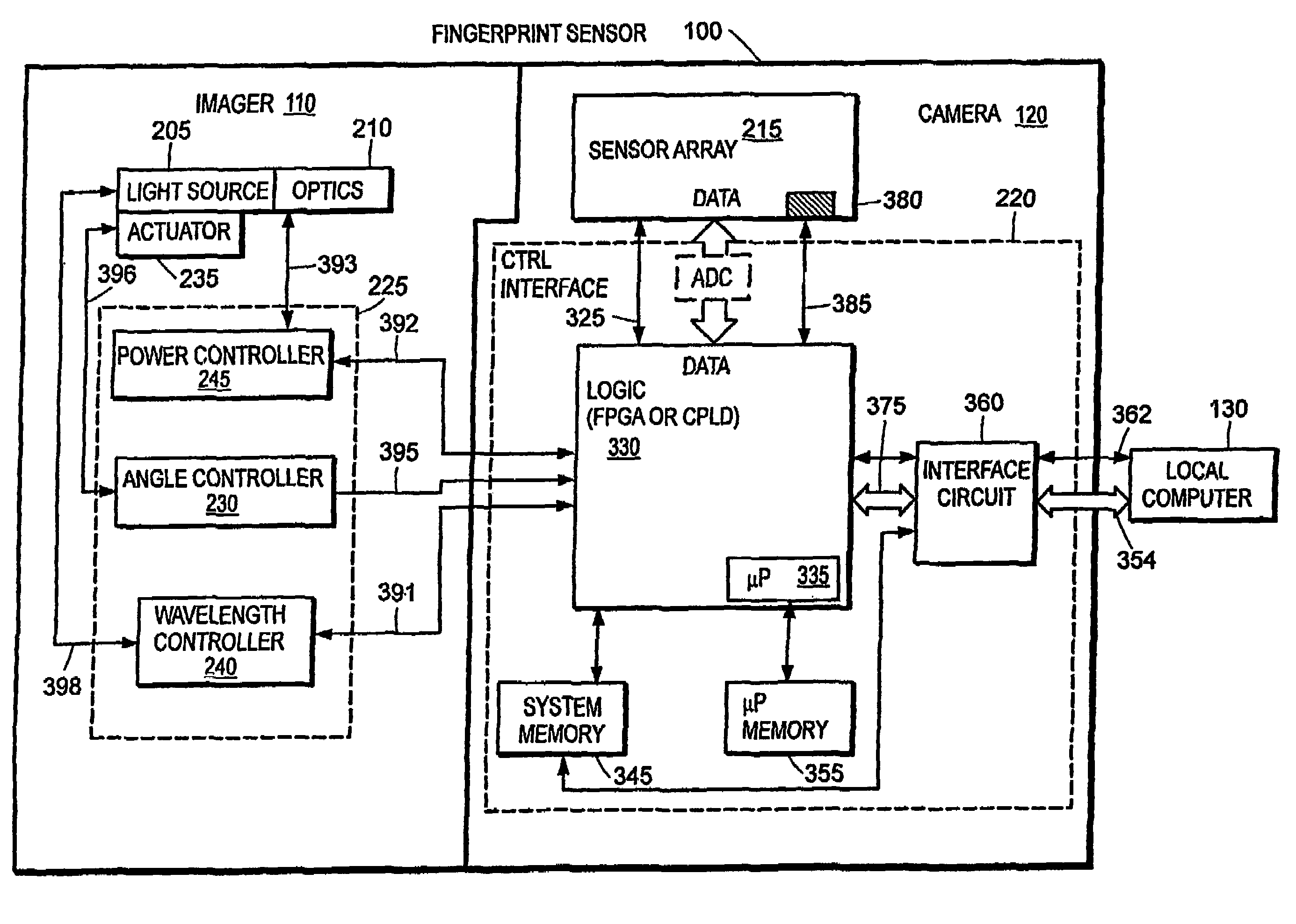
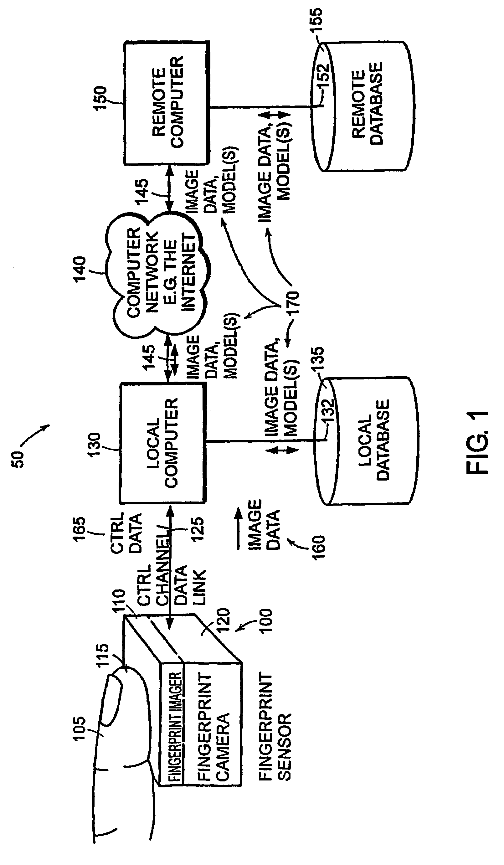
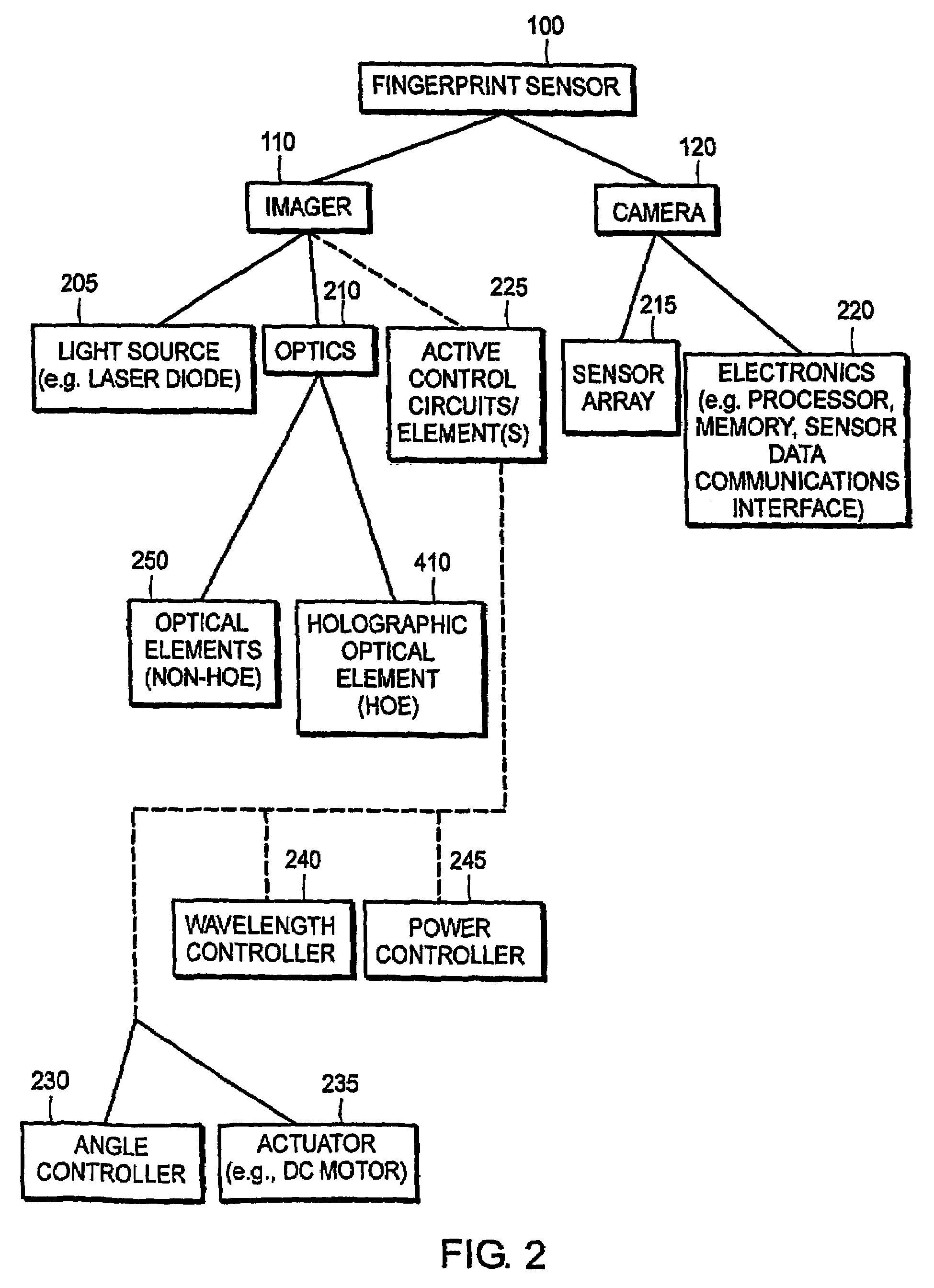
[0032]FIG. 1 is a system diagram in which an embodiment of a fingerprint sensor according to the principles of the present invention is employed. The fingerprint sensor 100 includes a fingerprint imager 110 and fingerprint camera 120. The imager 110 and camera 120 may be mechanically, electrically, and optically connected in a single “box.” A finger 105 or other topological surface of skin is placed on the fingerprint imager 110 at a “viewable” location by the imager 110 for acquisition of a fingerpri...


PUM


Abstract

An apparatus for image acquisition of topological features of the surface of skin. The apparatus comprises a waveguide, having an entrance edge and top and bottom surfaces; a light source, configured to direct a light beam at the entrance edge of the waveguide; a skin contact layer, disposed at or near the top surface of the waveguides; a holographic optical element (HOE), disposed at the top or at the bottom surfaces of the waveguide, configured to diffract the light beam incident from the light source to the skin contact layer; a sensor array, configured to detect light reflected from the surface of skin in contact with skin contact layer; and means for compensating for changes in the Bragg matching condition of the HOE due to temperature.

Description

RELATED APPLICATIONS[0001]This application is the U.S. National Stage of International Application No. PCT / US2004 / 019917, filed Jun. 21, 2004, published in English, and claims priority under 35 U.S.C. §119 or 365 to U.S. Provisional Application No. 60 / 480,008, filed on Jun. 21, 2003, U.S. Provisional Application No. 60 / 519,792, filed on Nov. 13, 2003 and U.S. Provisional Application No. 60 / 523,068, filed on Nov. 18, 2003. This application is related to the PCT Application entitled “Method and Apparatus for Processing Biometric Images” filed on Jun. 21, 2004 under the International Application No. PCT / US2004 / 019713. The entire teachings of the above applications are incorporated herein by reference.BACKGROUND OF THE INVENTION[0002]Growing concerns regarding domestic security have created a critical need to positively identify individuals as legitimate holders of credit cards, driver's licenses, passports and other forms of identification. The ideal identification process is reliable,...

Claims


Application Information

Patent Timeline
Patent Type & Authority Patents(United States)
IPC IPC(8): G06K9/74
CPCG06K9/00046G06V40/1324
Inventor WALDMAN, DAVID A.FEDELE, VINCENTINGWALL, RICHARD T.RAGUIN, DANIEL H.BERG, JOHN S.JOSEPH, JOBYKENT, DAVID L.
Owner APRILIS
Learn More