
Image and sound output system, image and sound data output device, and recording medium

a technology of image and sound data and output system, which is applied in the field of image and sound output system, image and sound data output device, and recording medium, can solve the problems of increasing the development cost and manufacture cost of each device, and viewers may feel uncomfortabl

Inactive Publication Date: 2010-06-01
COLUMBIA PEAK VENTURES LLC
View PDF11 Cites 5 Cited by
  • Summary
  • Abstract
  • Description
  • Claims
  • Application Information

AI Technical Summary

Benefits of technology

"The invention provides an image and sound data output system that can output image and sound data without the need for a specific communication program on the image display device. The system includes an image and sound data output device that separates the image and sound data, transmits the separated data to the display device through a transmission path, and synchronizes the output of the sound with the image using a sound output synchronization adjusting unit. This allows for optimal timing between the image and sound output. The system also includes a reproducing time recording unit that records the reproducing time of the image based on the resolution and bit rate of the image data. This eliminates the need for a separate program to process the delay time information, reducing development and manufacture costs. The system also allows for bidirectional communication between the display device and the image and sound data output device. Overall, the invention provides a more efficient and cost-effective system for outputting image and sound data."

Problems solved by technology

Therefore, in a case in which the data output device transmits the moving picture data to the image display device, and at the same time, a sound attached to the moving picture is reproduced and outputted, reproducing output of the sound data may be earlier than reproducing output of the moving picture, and moving picture output timing and sound output timing, that is, so-called lip-sync does not coincide, which results in applying uncomfortable feeling to viewers.
As a result, the development cost and the manufacture cost of each device may increase.

Method used


Image

  • Image and sound output system, image and sound data output device, and recording medium
  • Image and sound output system, image and sound data output device, and recording medium
  • Image and sound output system, image and sound data output device, and recording medium

Examples


first embodiment

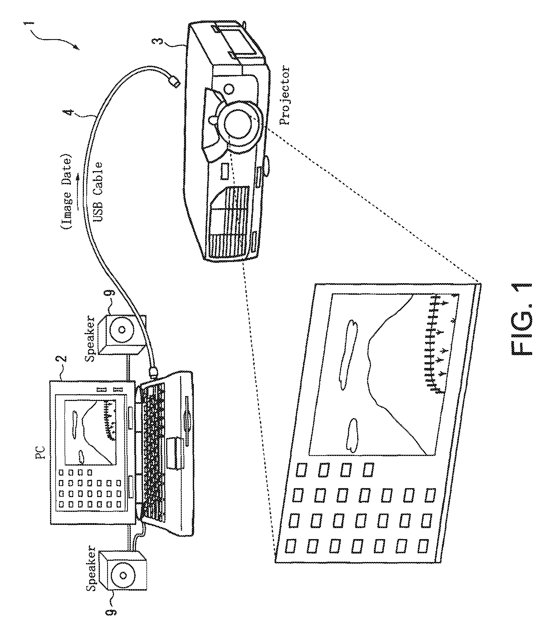
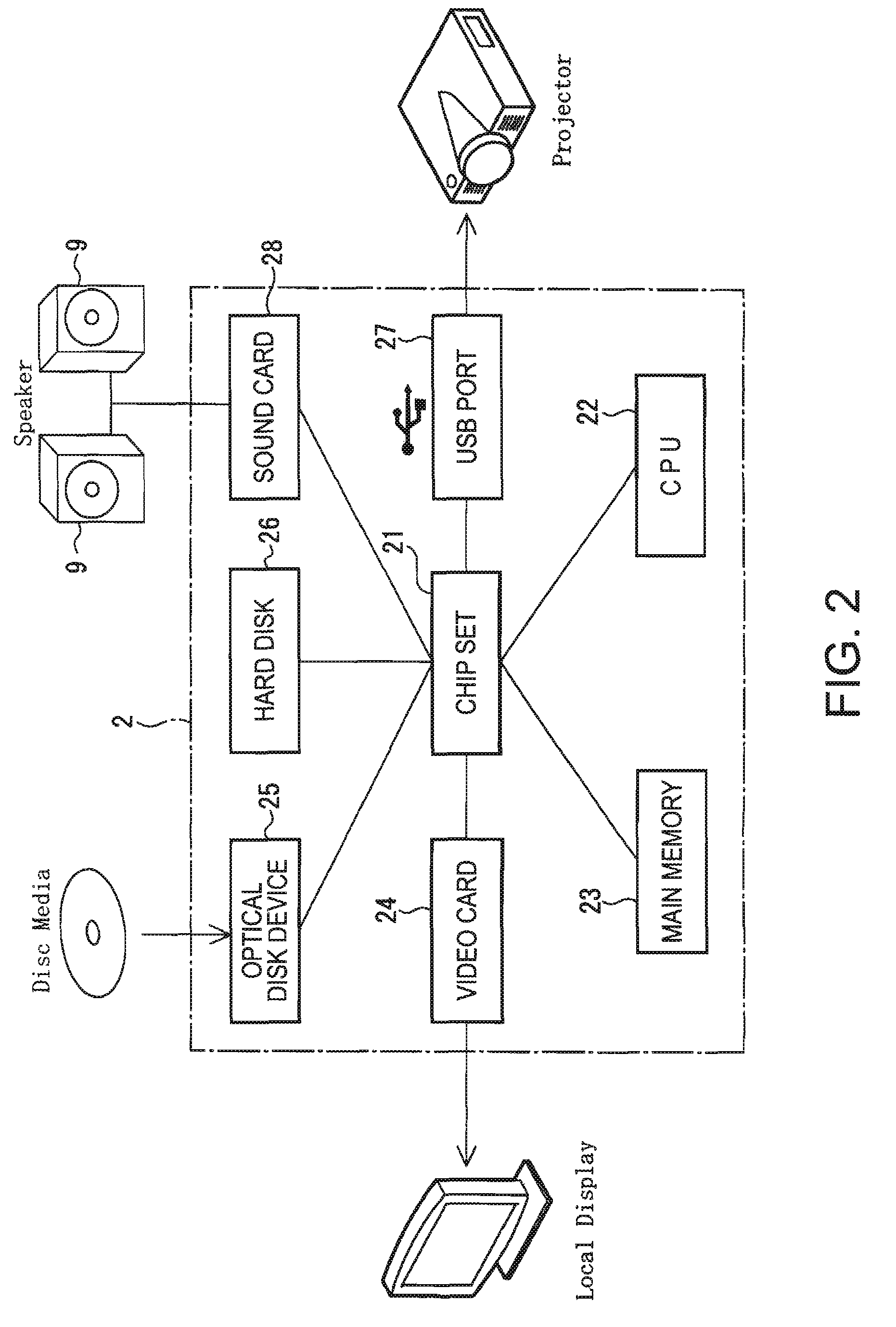
[0041]FIG. 1 shows an image and sound output system 1 according to a first embodiment of the invention. The image and sound output system 1 includes a computer 2 that serves as an image data output device, a projector 3 that serves as an image display device, and a USB cable 4 that serves as a transmission path connecting the computer 2 and the projector 3. In the image and sound output system 1, image data outputted by the computer 2 is inputted to the projector 3 through the USE cable 4, and an image on a local display of the computer 2 can be displayed on a screen as a projection image. Further, in the computer 2, a speaker 9 that is connected to a sound card built in the computer 2 is provided, and the speaker 9 outputs sounds according to a moving picture in the image projected by the protector 3.

[0042]The USB cable 4 is a cable that is based on standards, such as a USB 1.1, a USB 2.0, which enables bidirectional communication to be performed between a connecting apparatus and ...

second embodiment

[0116]Then, a second embodiment of the invention will be described. In the description below, the same constituent elements as those of the first embodiment are denoted by the same reference numerals, and the description thereof will be omitted.

[0117]In the first embodiment, as shown in FIG. 3, the sound output synchronization adjusting unit 228 adjusts the sound data output timing by the sound output adjusting time by delaying the output of the sound data stored in the delay buffer 281 constituting the sound card 28.

[0118]However, in the image output data device according to the second embodiment, as shown in FIG. 9, when outputting the sound data decoded by the audio decoder 230, the output timing of the sound data to the sound card 28 is adjusted on the basis of the sound output adjusting time.

[0119]That is, as shown in FIG. 9, the sound output synchronization adjusting unit 428 according to the second embodiment is constructed such that it delays the sound data decoded by the au...

third embodiment

[0121]Next, a third embodiment of the invention will be described.

[0122]In the first embodiment, the creating of the sound output adjusting time by the sound output adjusting time creating unit 227 is based on only the analyzed result by the moving picture data analyzing unit 224.

[0123]However, in the image and sound output system according to the third embodiment, as shown in FIGS. 10 and 11, when display setting is varied at the side of the image processing unit 7 of the projector, the setting information is outputted from the image processing unit 7 of the projector to the computer 8, and the computer 8 adds the time necessary for an image process according to the changed setting information, and creates the sound output adjusting time.

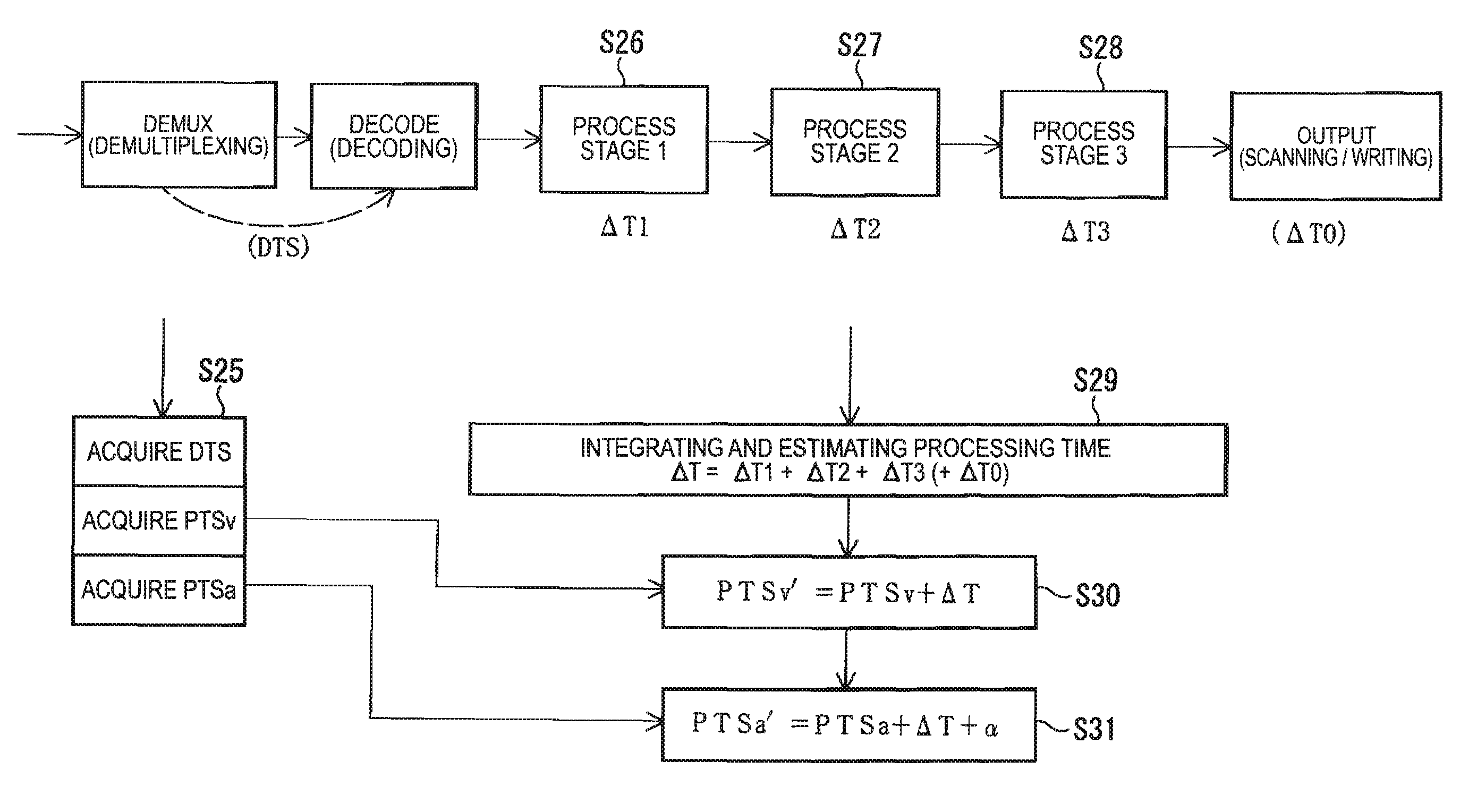
[0124]Specifically, as shown in FIG. 10, the image processing unit 7 of the projector includes an operation panel 71, a display state setting unit 72, and a setting information transmitting unit 73, in addition to the image processing unit 6 accord...


PUM

PropertyMeasurementUnit
timeaaaaaaaaaa
transmissionaaaaaaaaaa
delay timeaaaaaaaaaa

Abstract

An image and sound output system includes an image and sound data output device, and an image display device that is connected to the image and sound data output device through a transmission path. Further, the image and sound data output device includes an image and sound data separating unit, an image data transmitting unit that transmits the separated image data to the image display device, a sound data output unit that outputs the separated sound data, an image data analyzing unit that analyzes image data transmitted to the image display device by the image data transmitting unit, a sound output adjusting time creating unit, and a sound output synchronization adjusting unit. Furthermore, the image display device includes an image data receiving unit that receives image data transmitted by the image and sound data output device, an image processing unit.

Description

BACKGROUND[0001]1. Technical Field[0002]The present invention relates to an image and sound output system, to an image and sound data output device, and to a recording medium.[0003]2. Related Art[0004]In recent times, with an image process by a computer improved, a system has been suggested in which an image process having been generally performed by an image display device is performed by the computer, a format of image process data after the image process is converted into a digital format, the image process data is transmitted to an image display device, such as a projector, and an image is displayed by the image display device (for example, see JP-A-2004-69996 (FIG. 1)).[0005]In this system, a serial transmission interface, such as USB or IEEE 1394, is used as a transmission path. When comparing a cable for connecting the serial transmission interface with a general RGB video cable or the like according to the related art, since the cable for connecting the serial transmission i...

Claims


Application Information

Patent Timeline
Patent Type & Authority Patents(United States)
IPC IPC(8): H04N7/087G11B27/00H04N5/91H04N9/475H04N5/93H04N7/00G11B20/10H04N5/765H04N7/173H04N21/44H04N21/81
CPCH04N5/04H04N7/56H04N21/2368H04N21/4341H04N21/4307H04N21/434H04N21/4122H04N21/43072
Inventor YAMADA, NORIHIKO
Owner COLUMBIA PEAK VENTURES LLC
Learn More