
Method of designing machine

a technology of designing machine and design cycle, applied in the direction of battery/fuel cell control arrangement, instruments, batteries, etc., can solve the problems of increasing the development cost, shallow development history of fuel cell, and increasing the number of processes or costs needed for the design, so as to reduce the development cost and the development period of the new design period

Active Publication Date: 2019-01-03
TOYOTA JIDOSHA KK
View PDF0 Cites 3 Cited by
  • Summary
  • Abstract
  • Description
  • Claims
  • Application Information

AI Technical Summary

Benefits of technology

The patent text describes a method for designing a machine that mounts both a fuel cell stack and a drive motor. The method aims to reduce the development cost and period for new designs. The text also suggests using the same method for designing the fuel cell stack on another machine, which will save on development costs. The method further explains how to maintain the state of charge of the secondary battery during certain driving conditions to avoid short-term power output limitations. The overall technical effects are a reduction in development costs and period, as well as improved performance and efficiency of the machine.

Problems solved by technology

However, the development history of the fuel cell is shallow compared to that of the internal combustion engine.
For this reason, when the size or output of a fuel cell stack is optionally designed, the number of processes or a cost needed for the design become enormous.
For this reason, when a fuel cell vehicle is newly designed by referring the design concept of the hybrid vehicle, a possibility that a development cost may increase and a development period may lengthen occurs.

Method used


Image

  • Method of designing machine
  • Method of designing machine
  • Method of designing machine

Examples


Embodiment Construction

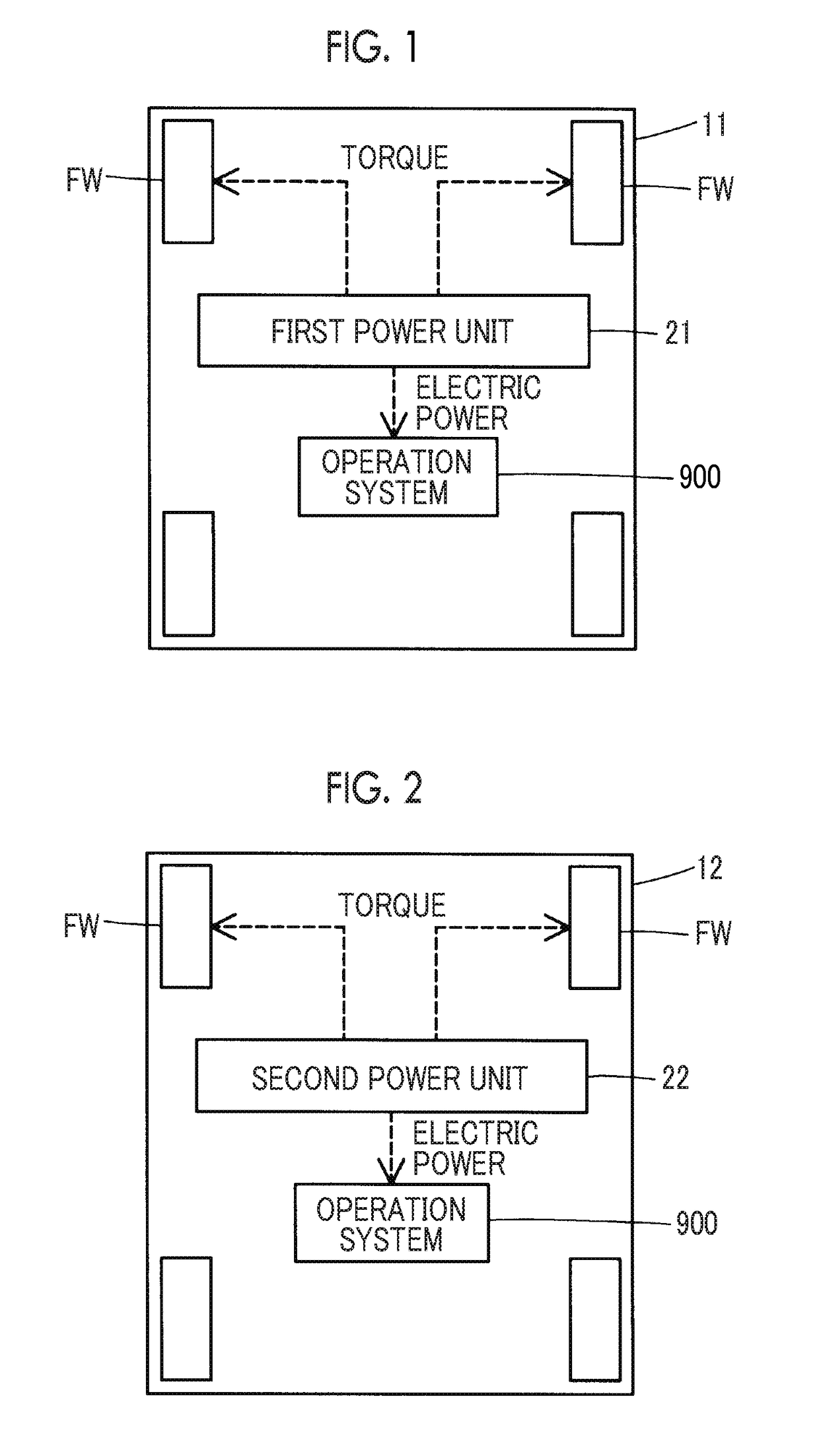
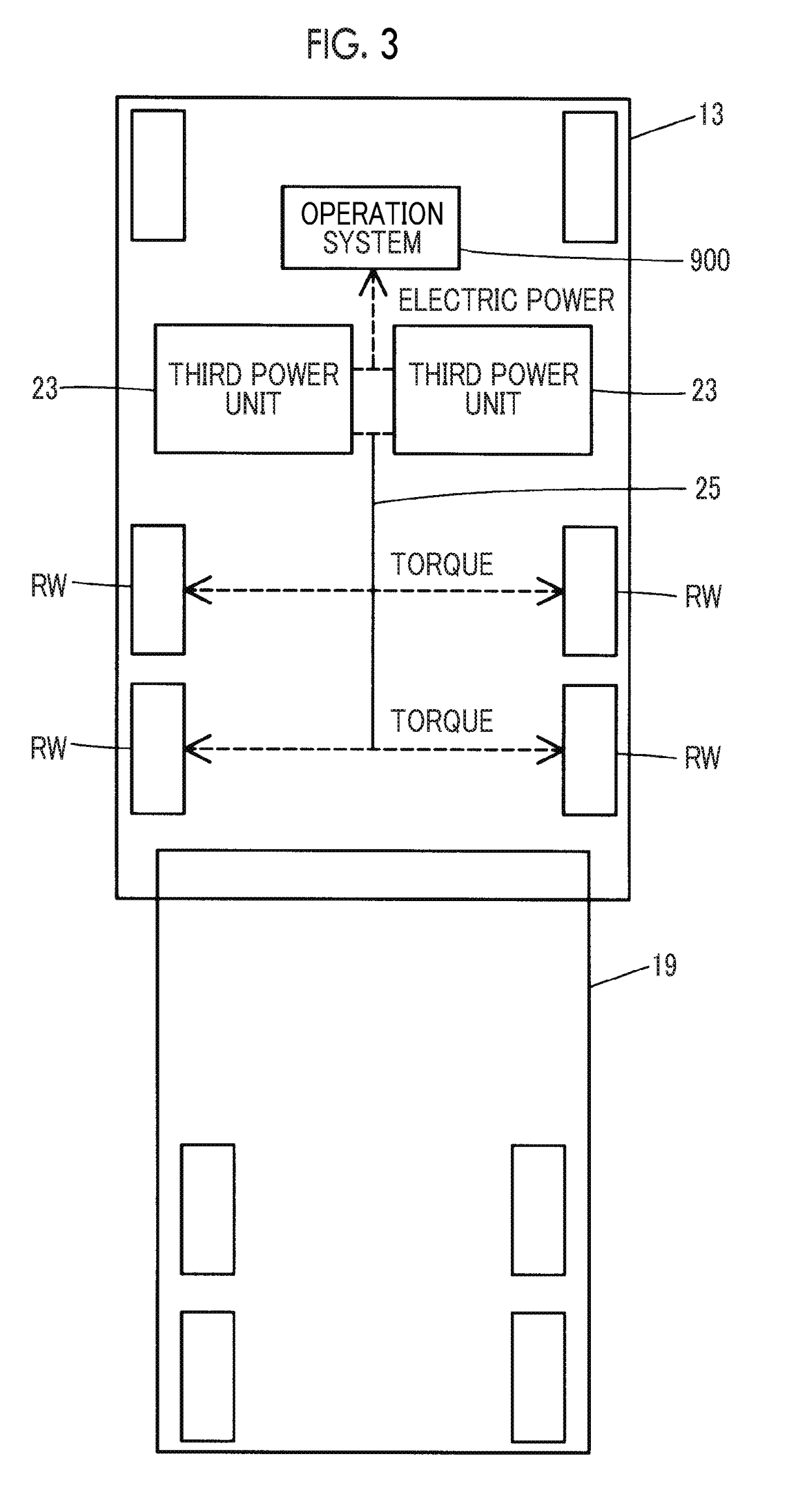
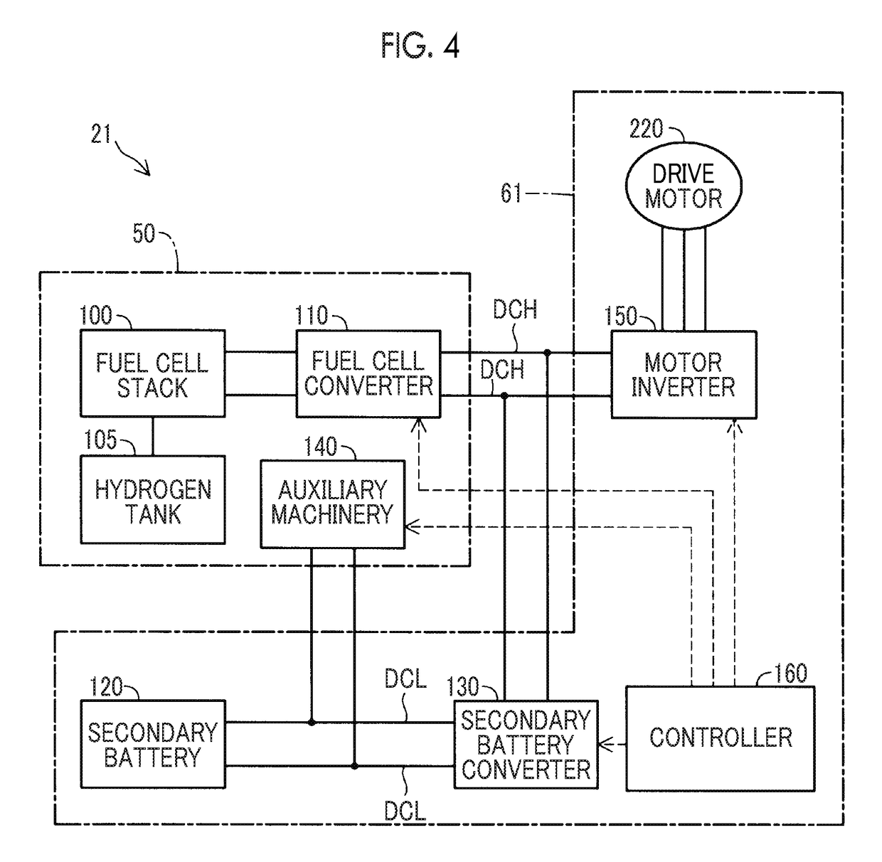
[0030]FIG. 1 shows a fuel cell vehicle 11. FIG. 2 shows a fuel cell vehicle 12. FIG. 3 shows a fuel cell vehicle 13. The fuel cell vehicles 11, 12 are passenger cars. The fuel cell vehicle 13 is a motor truck. The fuel cell vehicle 13 tows a trailer 19.

[0031]The fuel cell vehicle 11 is provided with a first power unit 21 and an operation system 900. The fuel cell vehicle 12 is provided with a second power unit 22 and the operation system 900. The fuel cell vehicle 13 is provided with two third power units 23, a propeller shaft 25, and the operation system 900. Each of the first power unit 21, the second power unit 22, and the two third power units 23 has a function of performing power generation by a fuel cell, as will be described later.

[0032]The operation system 900 is a generic term for devices that are operated by a driver for driving. The operation system 900 includes an accelerator pedal, a brake pedal, a steering wheel, and the like. The operation system 900 is not exactly th...


PUM

PropertyMeasurementUnit
speedaaaaaaaaaa
electric currentaaaaaaaaaa
of chargeaaaaaaaaaa

Abstract

A method of designing a machine on which a drive motor, a fuel cell stack, and a secondary battery are mounted includes: determining a maximum output of the drive motor to be a first output value and an output of the drive motor when a vehicle travels under a cruise condition to be a second output value; determining the number of fuel cell stacks to be mounted to be n; and determining a maximum output of the secondary battery to be a value obtained by subtracting a value obtained by multiplying a maximum output of the fuel cell stack by the n, from the first output value. A value obtained by multiplying the third output value by the n is equal to or larger than the second output value, and a value obtained by multiplying the third output value by (n−1) is less than the second output value.

Description

INCORPORATION BY REFERENCE[0001]The disclosure of Japanese Patent Application No. 2017-125996 filed on Jun. 28, 2017 including the specification, drawings and abstract is incorporated herein by reference in its entirety.BACKGROUND1. Technical Field[0002]This disclosure relates to a method of designing a machine on which a fuel cell stack and a motor are mounted.2. Description of Related Art[0003]Japanese Unexamined Patent Application Publication No. 2017-081319 (JP 2017-081319 A) discloses a hybrid vehicle that is provided with an internal combustion engine and a motor that is driven by power supply from a secondary battery.SUMMARY[0004]As a condition that has to be satisfied in a design of an automobile, a condition that a vehicle can travels under a cruise condition (hereinafter referred to as cruise traveling) can be mentioned. The cruise condition is a condition that the vehicle can continue to travel under a predetermined traveling condition for a predetermined time. The predet...

Claims


Application Information

Patent Timeline
Patent Type & Authority Applications(United States)
IPC IPC(8): G06F17/50H01M16/00H01M8/249B62D65/00
CPCG06F17/5095H01M16/006H01M8/249B62D65/00H01M2220/20H01M2250/20B60L15/20B60L2240/429B60K6/32B60L2200/36B60L2240/42B60L50/90B60L50/64B60L50/72B60L50/75Y02T90/14Y02T10/7072Y02E60/10Y02T90/40Y02T10/70B60L53/20B60L58/30B60W10/08B60W10/28B60W30/14B60Y2200/145B60W2300/12G06F30/15H01M8/24
Inventor NADA, MITSUHIRO
Owner TOYOTA JIDOSHA KK
Learn More