Fire hose holding apparatus

Inactive Publication Date: 2010-06-08
BERNIER CLAUDE
View PDF11 Cites 26 Cited by
  • Summary
  • Abstract
  • Description
  • Claims
  • Application Information

AI Technical Summary

Benefits of technology

[0020]A further object of the invention is to provide a fire hose holding appar

Problems solved by technology

As will be discussed below, no piece of prior art discloses a fire hose holding apparatus that has in addition to a handle, a squeezing clamp that enables the apparatus to be moved along the fire hose without disengaging the apparatus from the fire hose.
However, the hose gripping tool involves no moving parts and is not secured upon a hose by a locking clasp or a spring-loaded rubber insert as a means of securing the fire hose in place with respect to the holding apparatus.
The girth clamping ring does not include a handle, and also does not secure itself about a tubul

Method used


Image

  • Fire hose holding apparatus
  • Fire hose holding apparatus
  • Fire hose holding apparatus

Examples


Embodiment Construction

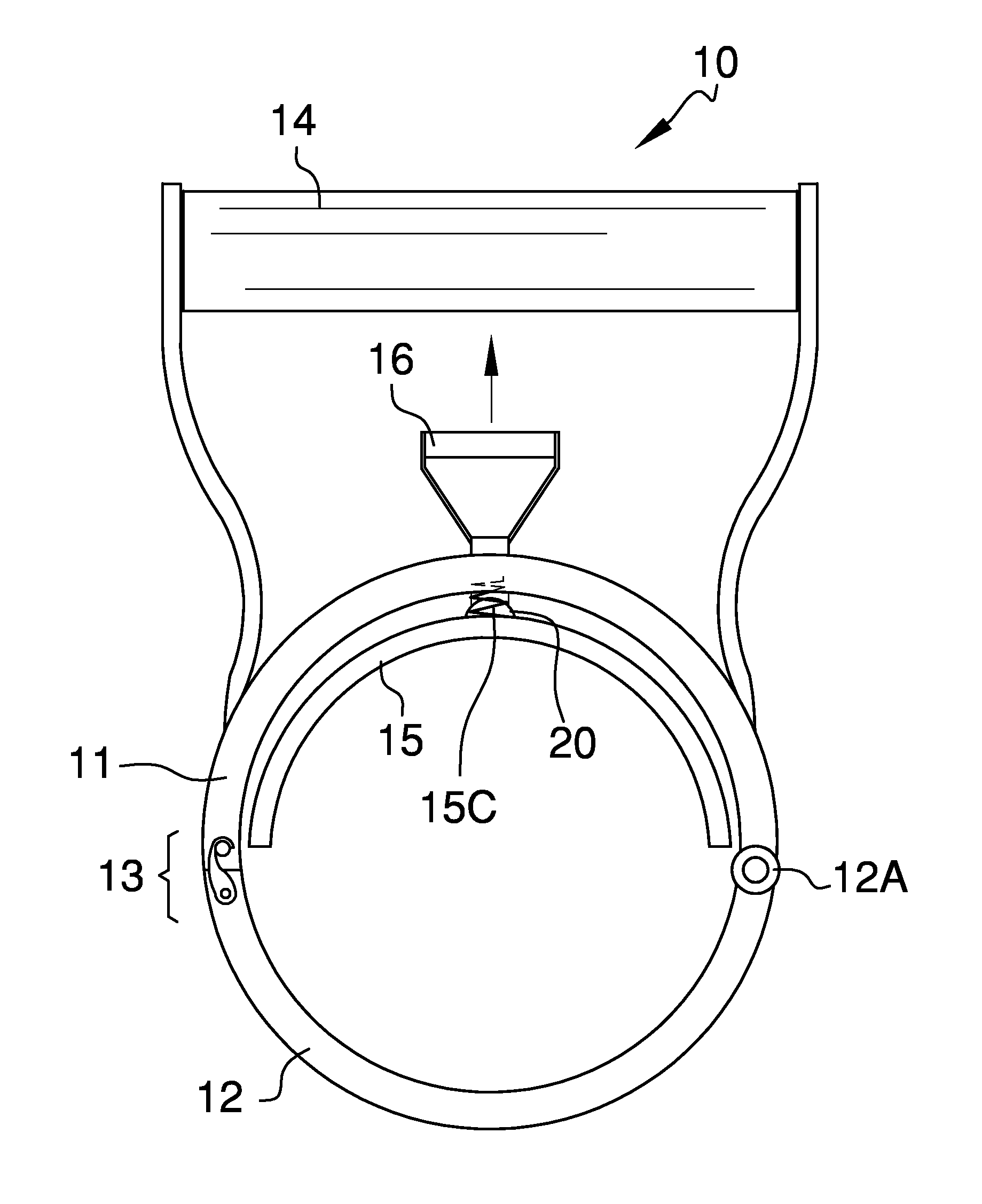
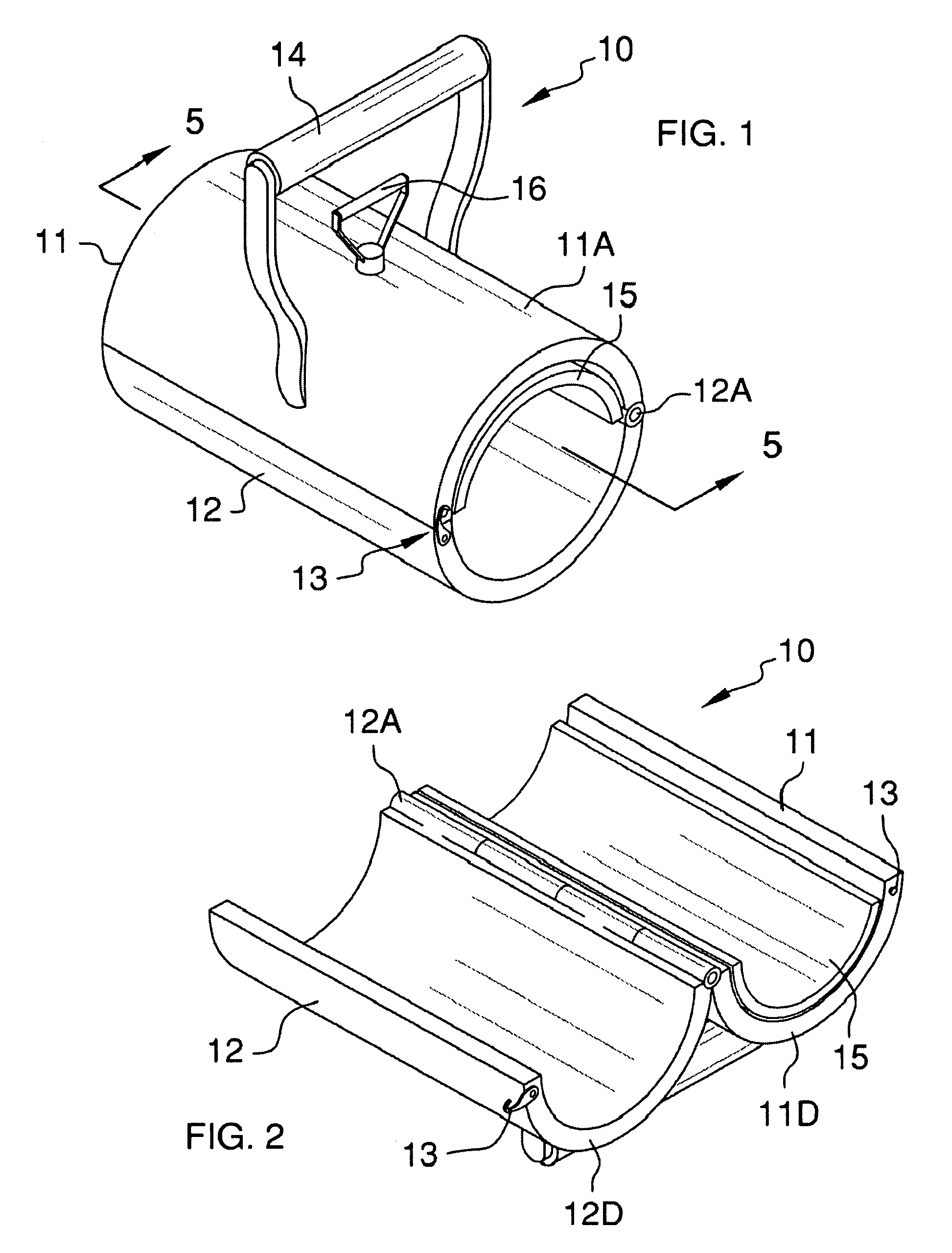
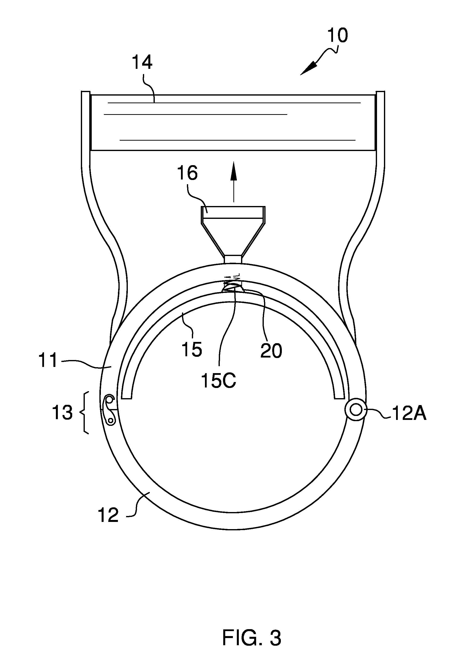
[0032]Detailed reference will now be made to the preferred embodiment of the present invention, examples of which are illustrated in FIGS. 1-6. A fire hose holding apparatus 10 (hereinafter invention) includes a top half 11, a bottom half 12, a locking clasp 13, a handle 14, a rubber insert 15, and a release handle 16.

[0033]The top half 11 is connected to the bottom half 12 via a hinge 12A. The top half 11 and the bottom half 12 may be considered, collectively, a clamp. The top half 11 has the handle 14 mounted at an outer surface 11A of the top half 11. The top half 11 also has a release handle hole 11B, which enables the release handle 16 to pass there through.

[0034]The rubber insert 15 has a release handle connectors 15A located on an outer surface 15B of the rubber insert 15. The rubber insert 15 also has a plurality of springs 15C mounted along the outer surface 15B. The top half 11 has a plurality of recesses 11C located on an inner surface 11D of the top half 11.

[0035]It shal...


PUM


Abstract

The invention is a fire hose holding apparatus that involves a hose clamp that involves two halves that are connected together via a hinge and a handle. Located along the interior of said two halves are rubber strips. The locking apparatus involves a locking clip on the opposite ends of the two halves and locking notch in the handle.

Description

CROSS REFERENCES TO RELATED APPLICATIONS[0001]Not ApplicableSTATEMENT REGARDING FEDERALLY SPONSORED RESEARCH[0002]Not ApplicableREFERENCE TO APPENDIX[0003]Not ApplicableBACKGROUND OF THE INVENTION[0004]A. Field of the Invention[0005]The present invention relates to the field of fire hose clamping devices for use by firemen when fighting a fire.[0006]B. Discussion of the Prior Art[0007]As a preliminary note, it should be stated that there is an ample amount of prior art that deals with fire hose holding apparatuses. As will be discussed below, no piece of prior art discloses a fire hose holding apparatus that has in addition to a handle, a squeezing clamp that enables the apparatus to be moved along the fire hose without disengaging the apparatus from the fire hose.[0008]The Ganung et al. (U.S. Pat. No. 4,470,177) discloses a fire hose clamp provided with a hand grip for firemen for use on a fire hose when fighting a fire to resist the back pressure acting on the hose. The device has...

Claims


Application Information

Patent Timeline
IPC IPC(8): B25G3/32
CPCA62C33/04Y10T16/469Y10T24/142B25G3/18
Inventor BERNIER, CLAUDE
Owner BERNIER CLAUDE
Why Eureka
Try Eureka