Method of operating a compactor machine via path planning based on compaction state data and mapping information

a technology of compaction state data and path planning, applied in the field of methods of operating a compactor machine, can solve the problems of requiring substantial operator or technician preparation time, affecting the operation efficiency of the compactor machine, and requiring a large amount of tim

Active Publication Date: 2010-06-08
CATERPILLAR INC
View PDF32 Cites 40 Cited by
  • Summary
  • Abstract
  • Description
  • Claims
  • Application Information

AI Technical Summary

Problems solved by technology

Despite such improvements, operating compacting machinery remains an often expensive, unpredictable and labor-intensive process.
Approaches relying upon operator judgment and perception, and even visual cues such as markers placed about the work area, have the potential for human error as well as requiring substantial operator or technician preparation time.
It is common for regions to be covered by a compactor machine more or fewer times than necessary in conventional approaches, wasting time and energy, and ultimately limiting work progress.
In other words, while more sophisticated electronic control and positioning systems can provide for more accurate information regarding the position of a compactor and, hence, its coverage of a given work area, they do not address irregularities, or general unpredictability in the work material's compaction response.
Because different regions of a work area may exhibit varying work material compaction responses, there are limitations to uniform coverage approaches, regardless of the extent of positioning accuracy and precision.
Although Sandstrom may have provided a useful insight, the approach does little, if anything, to guide decision-making based on the data.
In other words, while Sandstrom may be useful in gathering data, Sandstrom does not teach acting upon the data apart from the conclusions of a human operator or manager.
Moreover, Sandstrom does not recognize certain characteristics of work material compaction response that may be useful in planning subsequent compactor work.

Method used


Image

  • Method of operating a compactor machine via path planning based on compaction state data and mapping information
  • Method of operating a compactor machine via path planning based on compaction state data and mapping information
  • Method of operating a compactor machine via path planning based on compaction state data and mapping information

Examples


Embodiment Construction

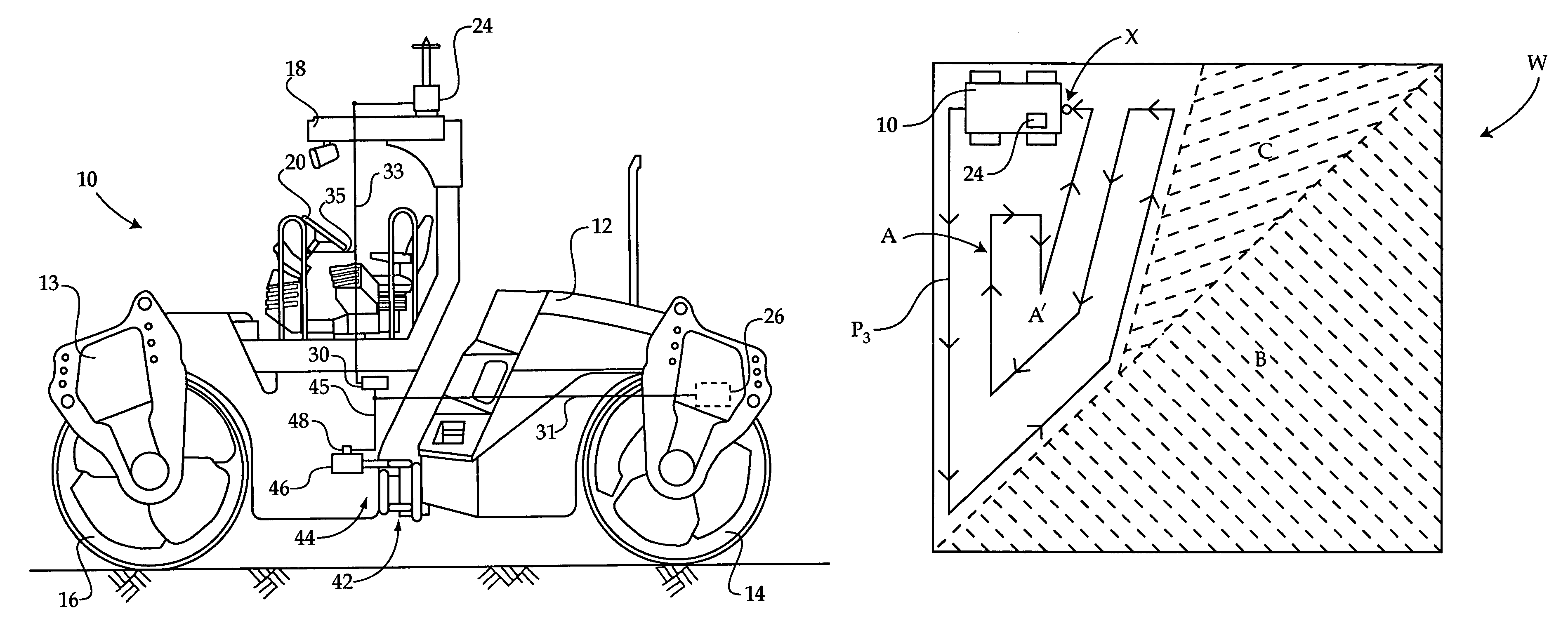
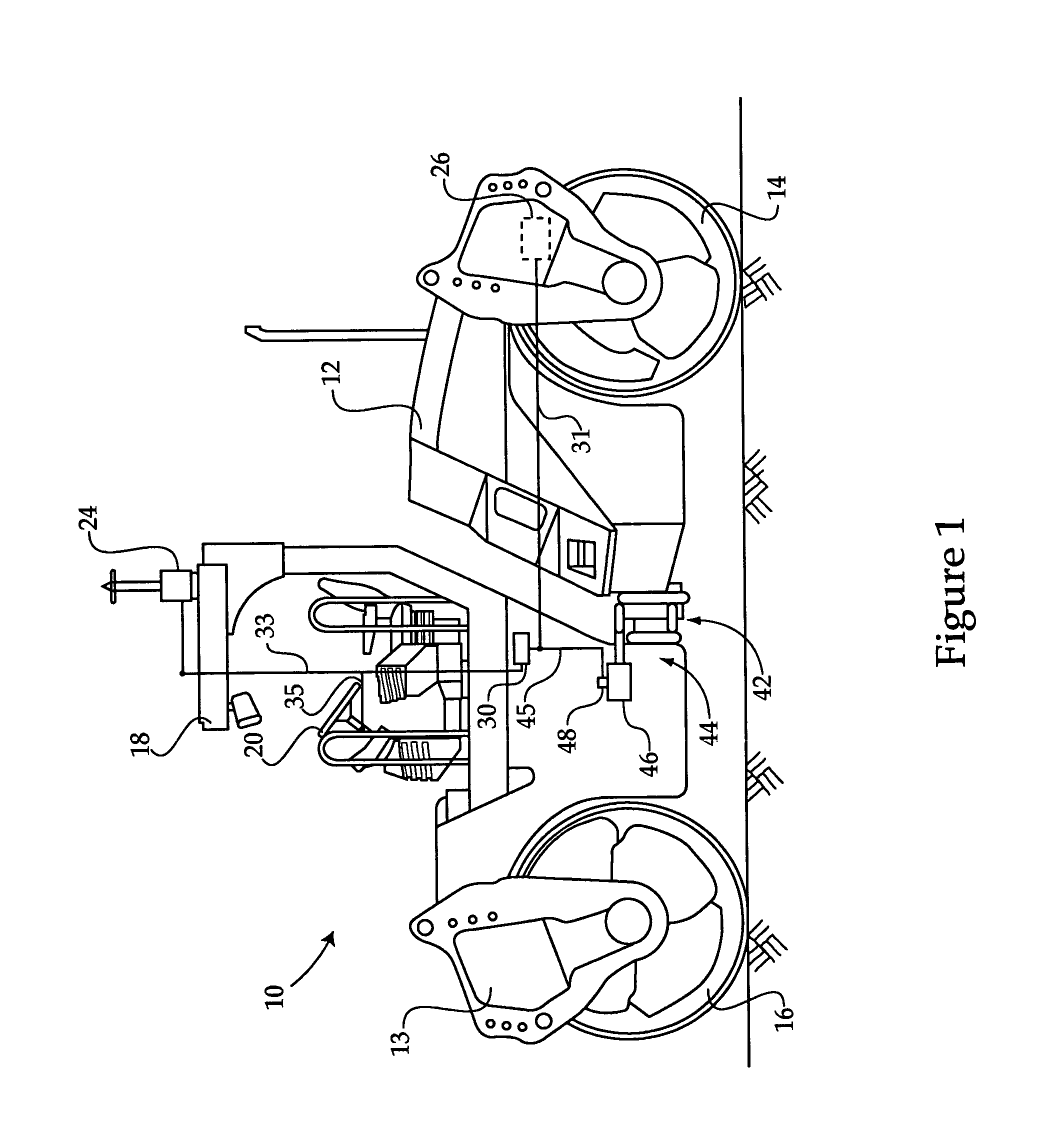
[0017]Referring to FIG. 1, there is shown a compactor machine 10 including a frame having first and second frame units 12 and 13. Compactor 10 may further include an operator cabin 18 having therein an operator input device 20 such as a steering wheel or similar control device. A position signal receiver 24 may be mounted on one of frame units 12 and 13, which is configured to receive position signals from a signal transmitter such as a global positioning satellite(s), or another system such as a ground based laser positioning system. Compactor 10 may further include an electronic controller 30 configured to control various aspects of compactor operation, as described herein. Compactor 10 may also include at least one compaction state sensor 26. Electronic controller 30 may be configured to utilize mapping or position information received via receiver 24 in conjunction with work material compaction response data input to electronic controller 30 from sensor 26 to navigate within a w...


PUM


Abstract

A method of operating a compactor machine includes moving the compacting machine within a work area and determining a compaction response disconformity exists between at least two regions of the work area. The method includes generating a compactor navigation signal responsive to the compaction response disconformity. A method of compacting a work area may include determining a work material compaction response associated with at least one region of the work area is aberrant, and maneuvering the compactor machine within the work area responsive to a signal associated with the aberrant compaction response. A system for compacting a work area includes a compactor machine and an electronic controller configured via a compactor maneuvering control algorithm to detect an aberrant work material compaction response in a region of the work area and responsively generate a compactor navigation signal.

Description

TECHNICAL FIELD[0001]The present disclosure relates generally to methods of operating a compactor machine to compact a work material in a work area, and relates more particularly to such a method wherein work material compaction response and compactor position information are used to determine a desired travel path for maneuvering a compactor machine within the work area.BACKGROUND[0002]Many construction, road building and related endeavors employ compactor machines to compact work material such as earth, asphalt, gravel, mixtures, etc. so that the work material will be suitable for an end purpose. Compaction may also be used to reduce the volume of work material, as in the case of materials such as landfill trash. A traditional approach to compacting work material in a given work area is to pass a compactor machine uniformly across the work area, using operator judgment, ground-based visual markers, or electronic positioning systems to indicate the progress of compacting the work m...

Claims


Application Information

Patent Timeline
Patent Type & Authority Patents(United States)
IPC IPC(8): E01C23/01G01S19/25
CPCE01C19/288
Inventor CONGDON, THOMAS M.CORCORAN, PAUL T.
Owner CATERPILLAR INC
Why Eureka
Try Eureka