Pattern detection using an optical navigation device

a navigation device and optical navigation technology, applied in the field of pattern recognition, can solve the problems of relatively expensive specialized pattern detection devices, relatively sophisticated and expensive prior pattern detection devices, and relatively expensive patterns

Active Publication Date: 2010-06-08
PIXART IMAGING INC
View PDF9 Cites 11 Cited by
  • Summary
  • Abstract
  • Description
  • Claims
  • Application Information

AI Technical Summary

Benefits of technology

[0004]An optical navigation device is disclosed that is capable of performing pattern detection. An optical navigation device according to the present teachings includes an image sensor that acquires a series of images of a surface and an image buffer for holding a template and a processor that detects a pattern on the surface by comparing the series of images to the template. The form factor of an optical navigation device enables its use as a pattern detection device for a wide variety of patterns on a wide variety of surfaces having a wide variety of forms. In addition, an optical navigation device according to the present teachings may be implemented as a relatively inexpensive pattern detection device by using pre-existing mechanisms in an optical navigation device.

Problems solved by technology

Prior pattern detection devices may be relatively sophisticated and expensive devices.
Unfortunately, specialized pattern detection devices may be relatively expensive.
Unfortunately, a personal computer with a scanner may be a relatively expensive way of performing pattern detection.
In addition, a scanner for a personal computer may not be useful for detecting patterns on a medium that cannot be fed into a scanner, e.g. images on walls, boxes, or other surfaces.

Method used


Image

  • Pattern detection using an optical navigation device
  • Pattern detection using an optical navigation device

Examples


Embodiment Construction

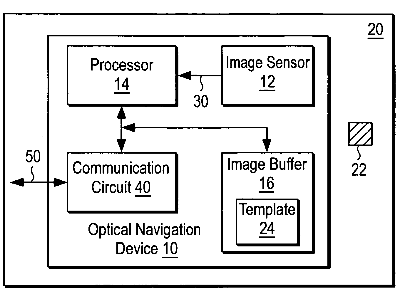
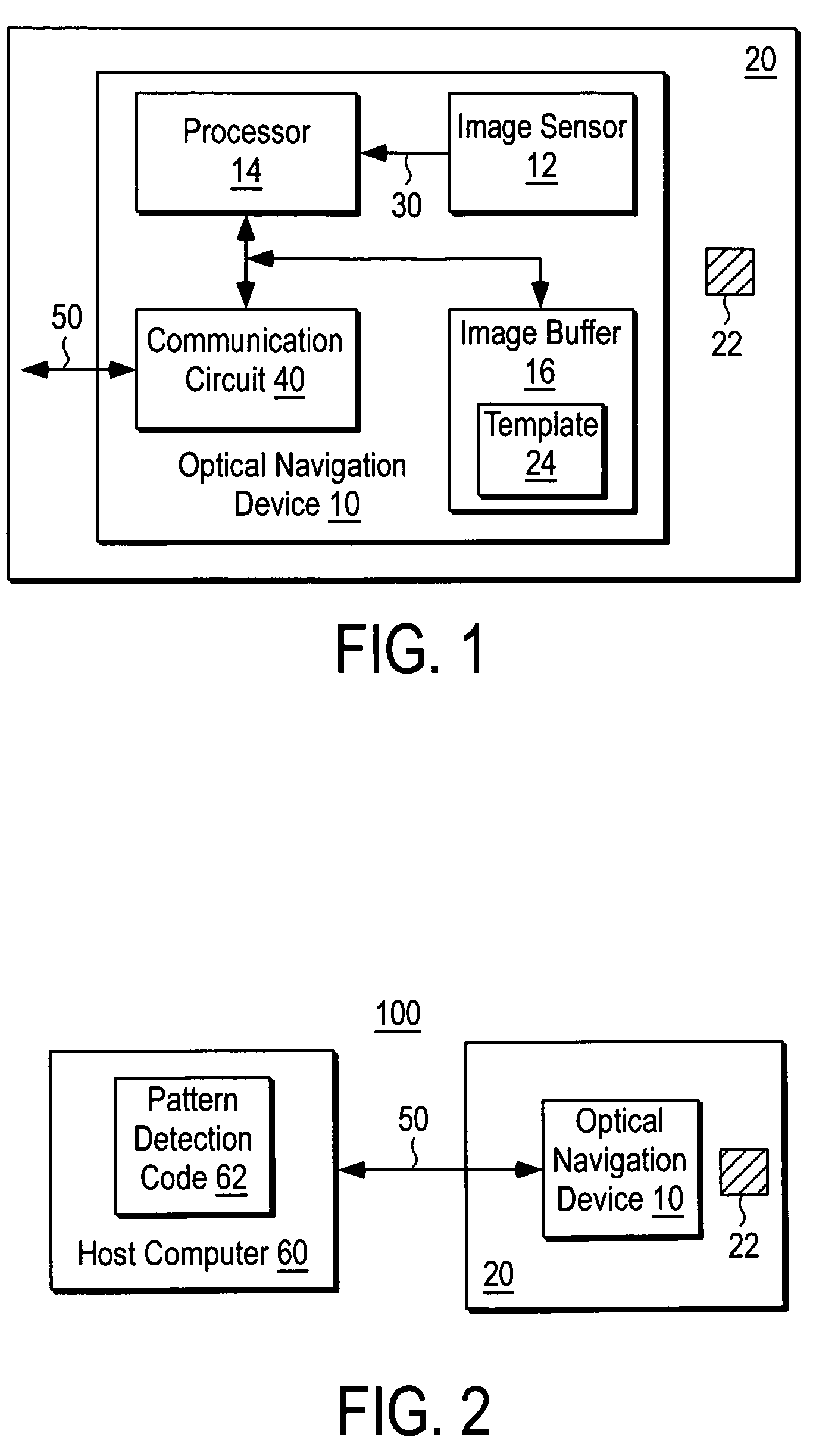
[0009]FIG. 1 shows an optical navigation device 10 according to the present teachings. The optical navigation device 10 includes a image sensor 12, a processor 14, an image buffer 16, and a communication circuit 40. The optical navigation device 10 in the example shown detects a pattern 22 on a surface 20.

[0010]The optical navigation device 10 may be an optical navigation mouse for a computer or a light pen input device for a computer, to name a couple of examples. The image sensor 12, the processor 14, and the communication circuit 40 may be pre-existing mechanisms in the optical navigation device 10 for performing optical navigation functions, e.g. mouse pointing functions, for a host computer. In some embodiments, the power of the processor 14 may be augmented over that used to perform normal navigation functions, e.g. by increasing its speed, level of integration, memory capacity, etc., to support pattern detection.

[0011]The surface 20 may be any type of surface. Examples of the...


PUM


Abstract

An optical navigation device that is capable of performing pattern detection. An optical navigation device according to the present teachings includes a image sensor that acquires a series of images of a surface and an image buffer for holding a template and a processor that detects a pattern on the surface by comparing the series of images to the template. The form factor of an optical navigation device enables its use as a pattern detection device for a wide variety of patterns on a wide variety of surfaces having a wide variety of forms.

Description

BACKGROUND[0001]Pattern detection, also known as pattern recognition, may be defined as a machine vision technique for detecting visual patterns, e.g. patterns printed on paper or other media. Pattern detection may have a variety of applications. Example applications of pattern detection include reading bar codes, verifying watermarks, optical character recognition, as well as biometric applications such as face recognition, fingerprint recognition, etc.[0002]Prior pattern detection devices may be relatively sophisticated and expensive devices. For example, a pattern detection device may be implemented as a specialized device having optics and an image sensor for acquiring images and a processor and code for performing pattern recognition on the acquired images. Unfortunately, specialized pattern detection devices may be relatively expensive.[0003]Pattern detection may be performed using a computer system, e.g. a personal computer, that is equipped with an appropriate imaging device...

Claims


Application Information

Patent Timeline
Patent Type & Authority Patents(United States)
IPC IPC(8): G09G5/00
CPCG06F3/0317
Inventor XIE, TONG
Owner PIXART IMAGING INC
Why Eureka
Try Eureka