
Lens positioning assembly

a technology of positioning assembly and lens, which is applied in the direction of mounting, microscope, optics, etc., can solve the problem that the piezoelectric element cannot move the microscope objective lens and its support assembly in relatively small amounts, and achieves the effects of small reduction in imaging time, fast rate, and great movement distan

Active Publication Date: 2010-06-08
FFEI LTD
View PDF18 Cites 0 Cited by
  • Summary
  • Abstract
  • Description
  • Claims
  • Application Information

AI Technical Summary

Benefits of technology

[0004]With this new arrangement, we have found that it is possible to achieve much greater movement distances, for example up to 6 mm, but still at a very fast rate so that there is little reduction in imaging time. Accelerations in the order of 27 ms−2 can be achieved.
[0005]In particular, a key benefit of the system is that it allows a heavy lens to be driven at high accelerations along its optical axis. To do this, the force from the actuator acts along the optical axis while the reflector turns the optical axis. It will be noted that the reflector does not move with the objective lens so that there is a fixed path from the reflector to a remote detector or the like.
[0011]A preferred movement actuator is a linear actuator such as a voice coil actuator or piezo device. This is particularly suited to the relatively small movements that the objective lens support assembly is required to undergo but is very accurate.

Problems solved by technology

The problem with this known arrangement is that a piezoelectric element can only move the microscope objective lens and its support assembly by relatively small amounts, typically less than 500 microns and at relatively low accelerations while requiring purpose built actuators.

Method used


Image

  • Lens positioning assembly
  • Lens positioning assembly
  • Lens positioning assembly

Examples


Embodiment Construction

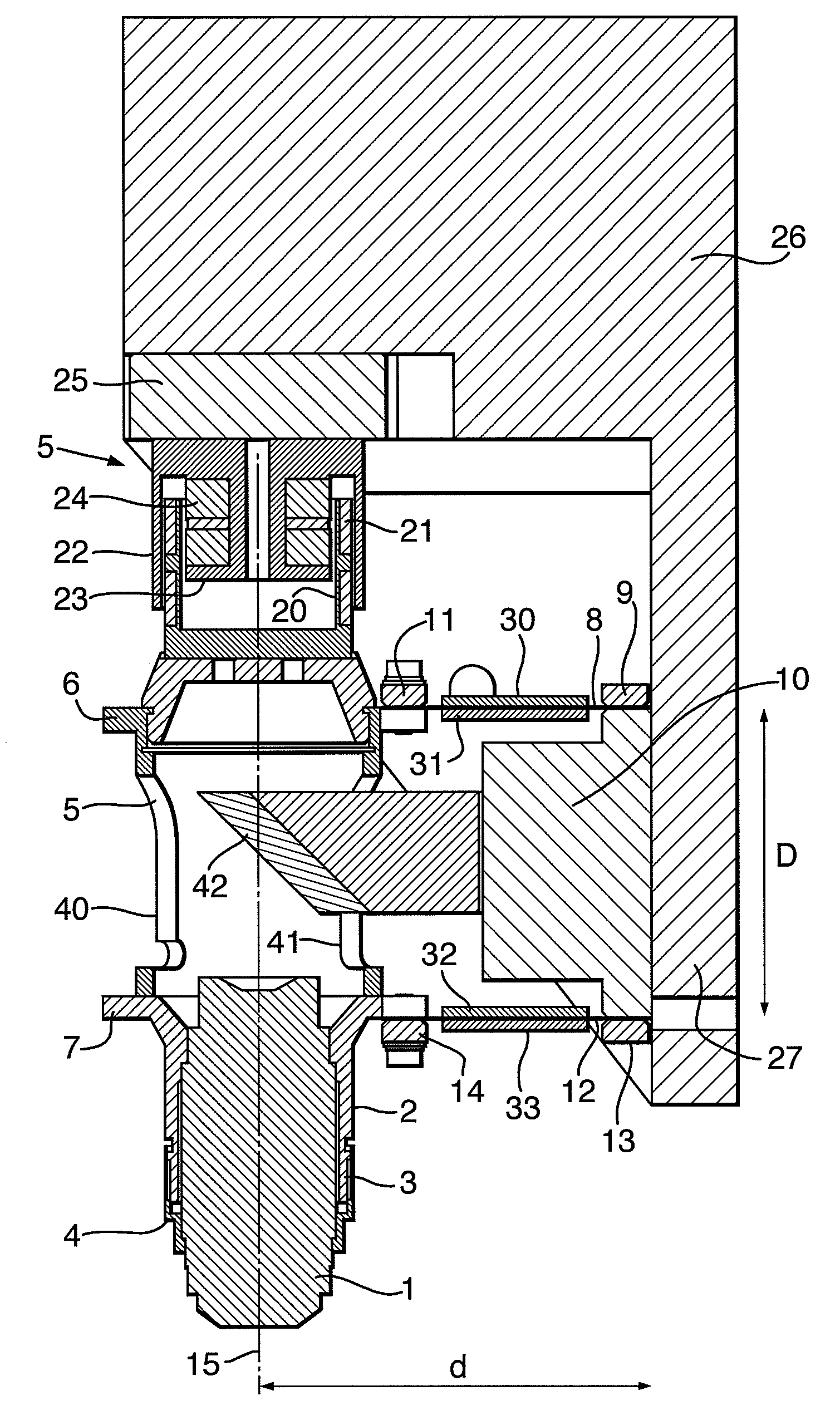
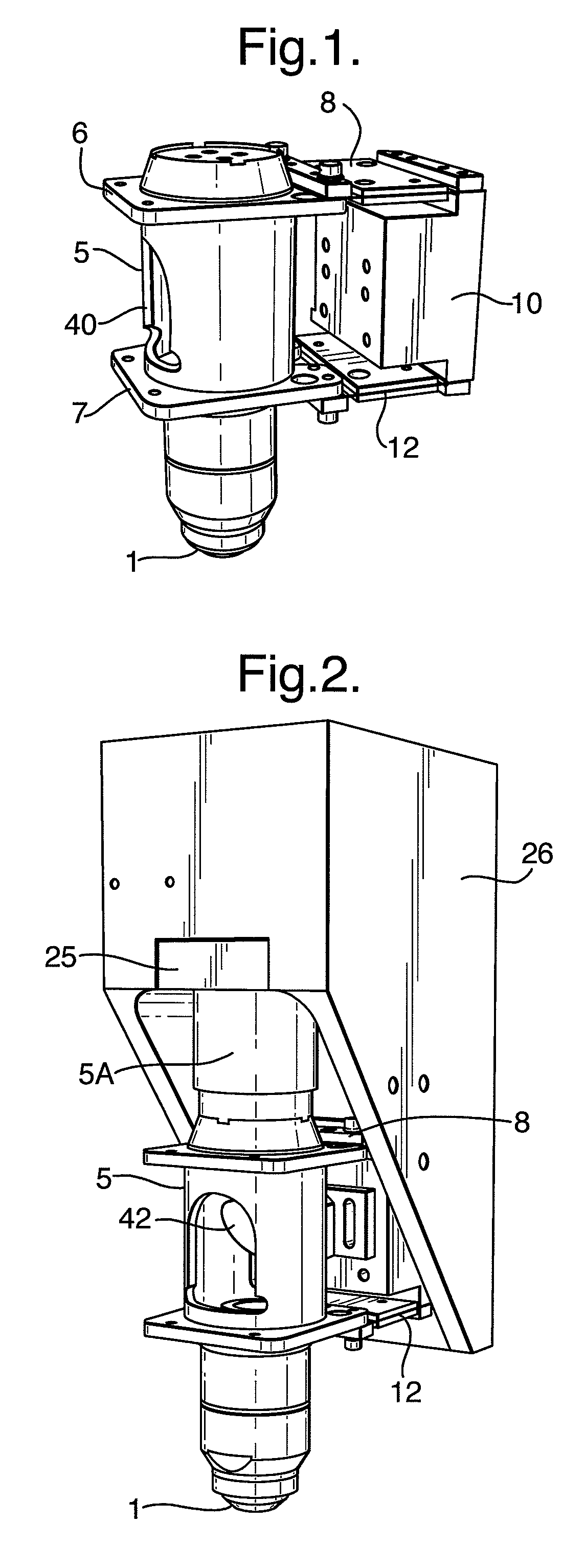
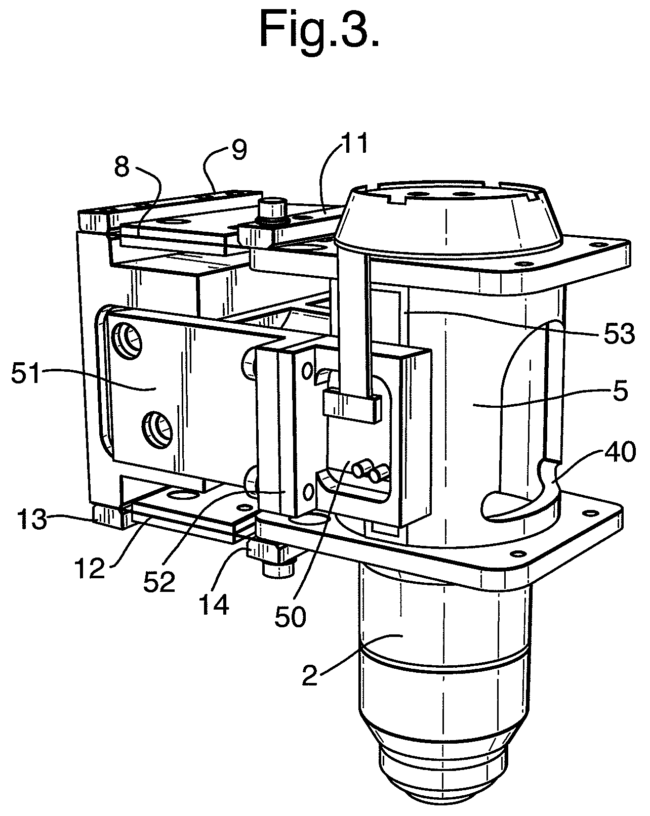
[0018]The objective lens positioning assembly is shown in the drawings with an objective lens 1 mounted to it. As can be seen most clearly in FIG. 4, the objective lens 1 is supported in a barrel 2 having an external screw thread 3 by means of an internally screw threaded retaining nut 4. The barrel 2 is formed at the lower end of a tube 5 having upper and lower flanges 6,7.

[0019]An upper leaf spring 8 is bolted by a bar 9 at the first end to a support member 10 and at its second end is bolted by a bar 11 to the flange 6.

[0020]A leaf spring 12 is bolted by a bar 13 at a first end to the support member 10 and is bolted by a bar 14 at a second end to the flange 7.

[0021]The distance D between the first ends of the leaf springs 8,12 is the same as the distance D between the second ends of the leaf springs 8,12. D is 66 mm in one example. Similarly, the distance between the point at which each leaf spring 8,12 is fixed at its first end, to the optical axis 15 of the objective lens 1 is t...


PUM


Abstract

A microscope objective lens positioning assembly comprises a lens mounting member to which a microscope objective lens defining an optical axis is mounted; a support member; and a pair of leaf springs. Each leaf spring has first and second ends, the first ends of the leaf springs being secured to upper and lower aligned locations respectively on the support member, and the second ends of the leaf springs being secured to corresponding upper and lower locations respectively on the lens mounting member whereby the two leaf springs, the optical axis of the objective lens, and a line between the upper and lower aligned locations on the support member define a parallelogram, the leaf springs flexing in use in response to movement of the lens mounting member.

Description

FIELD OF THE INVENTION[0001]The invention relates to a lens positioning assembly, for example for a microscope objective lens.BACKGROUND OF THE INVENTION[0002]In the field of microscopes used for scanning biological samples and the like, it is often necessary to refocus the objective lens rapidly in order to compensate for variations in thickness of the biological sample being inspected. This is done by moving the microscope objective lens relative to a support member so as to adjust the distance between the objective lens and the sample. It is difficult to move an objective lens rapidly because the lens and its support assembly typically weigh over 100 grams but in the past this has been achieved by mounting the objective lens support assembly to a piezoelectric element and applying a suitable control signal to the element to cause the element to move the support assembly. The problem with this known arrangement is that a piezoelectric element can only move the microscope objective...

Claims


Application Information

Patent Timeline
Patent Type & Authority Patents(United States)
IPC IPC(8): G02B7/02
CPCG02B7/08G02B21/241G02B21/04
Inventor GRIFFITHS, PAUL SCOTTHAWES, WILLIAM ROLAND
Owner FFEI LTD
Learn More