Head unit for a medical/surgical personal protection system with a head band and a ventilation unit that is adjustably position relative to the head band

a technology of ventilation unit and head unit, which is applied in the direction of protective garments, chemical protection, breathing protection, etc., can solve the problems of difficult to provide workable light, individual wearing the system may have to speak loudly, etc., and achieve the effect of imposing only a minimal strain on the wearer

Active Publication Date: 2010-06-15
STRYKER CORP
View PDF17 Cites 67 Cited by
  • Summary
  • Abstract
  • Description
  • Claims
  • Application Information

AI Technical Summary

Benefits of technology

[0008]The system of this invention includes a ventilation unit for supplying ventilation air underneath the toga / hood of wearer. There is a light unit. The light unit has a light source positioned in line with the air discharged from the ventilation unit. This arrangement minimizes the build up of heat around the light unit.
[0010]The system of this invention also has a head unit that substitutes for a conventional helmet. The head unit includes a head band and a ventilation unit that is suspended above the head band. The ventilation unit is adjustably positioned relative to the head band. This allows the ventilation unit to be positioned relative to the head of the wearer so it is located where it will impose only a minimal strain on the wearer.

Problems solved by technology

However, there are some limitations associated with their use.
This means an individual wearing the system may have to speak loudly, even shout, to be heard.
Furthermore, while it is known to provide light with the helmet, it has proven difficult to provide a workable light.
This both limits the mobility of the individual and requires other operating room personnel to navigate around the tether.
This heat can cause the temperature beneath the toga / hood to rise to an uncomfortable level.
Moreover, the helmet and the equipment it supports, places a load on the head of the wearer.
Over time this load can impose an appreciable strain on the muscles and skeletal structure.

Method used


Image

  • Head unit for a medical/surgical personal protection system with a head band and a ventilation unit that is adjustably position relative to the head band
  • Head unit for a medical/surgical personal protection system with a head band and a ventilation unit that is adjustably position relative to the head band
  • Head unit for a medical/surgical personal protection system with a head band and a ventilation unit that is adjustably position relative to the head band

Examples


Embodiment Construction

I. Overview

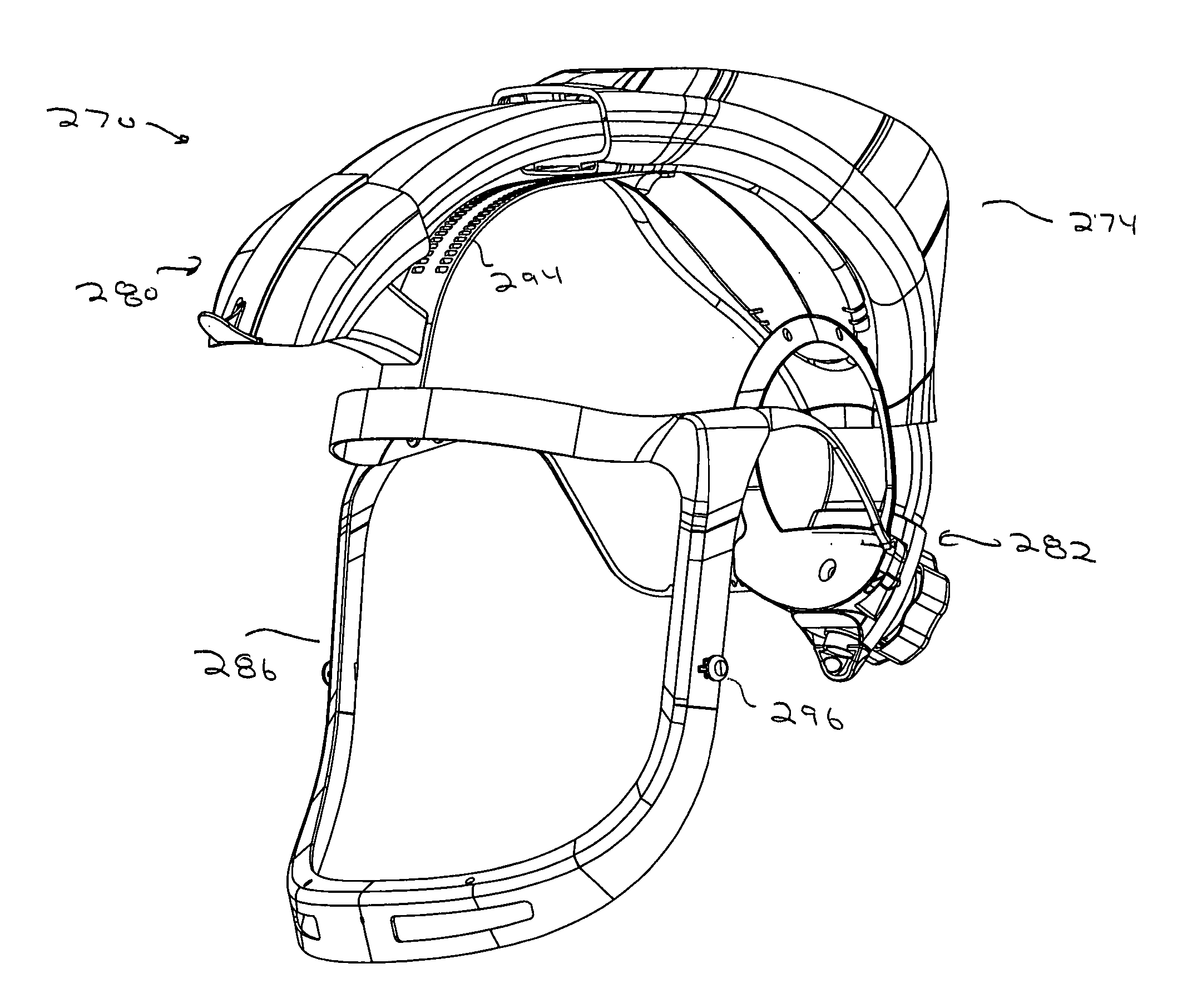
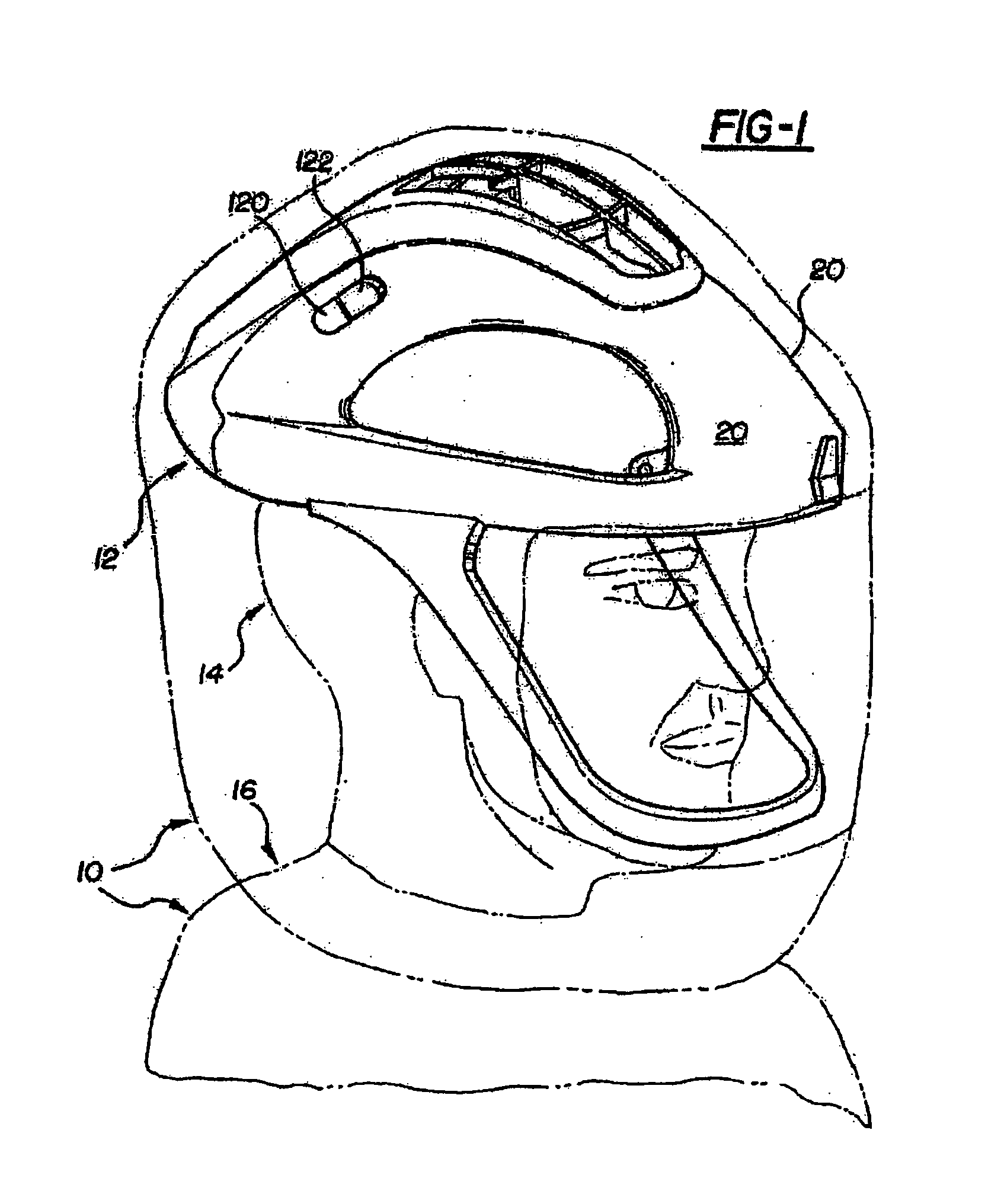
[0068]Referring to the Figures, wherein like numerals indicate like or corresponding parts throughout the several views, a personal protection system is generally shown at 10.

[0069]The personal protection system 10 is adapted from the personal protection system 10 disclosed in U.S. Pat. No. 6,481,019 to Diaz et al. and U.S. Provisional Patent Application No. 60 / 664,900, both of which are hereby incorporated by reference. The personal protection system 10 of the present invention is implemented as a helmet assembly 12 mountable to the head 14 of a user, as shown in FIG. 1.

[0070]The personal protection system 10 filters air between the head 14 and body 16 of a user, e.g., a medical professional, and an environment external to the user. The helmet assembly 12 distributes air about the head 14 of the user as will be described below. More specifically, the helmet assembly 12 distributes air toward both a front of the head 14, i.e., a face of the user, and a back of the head 14...


PUM


Abstract

A personal protection system for providing a sterile barrier around medical / surgical personnel. The system includes a head unit over which a hood or a toga suspended. Internal to the head unit is a ventilation fan, a light for illuminating the surgical field and communications system for communicating with others. The head unit includes a head band. The ventilation fan is adjustably mounted to the head band so it can be positioned at a location to minimize the strain imposed on the wearer.

Description

RELATIONSHIP TO EARLIER FILED APPLICATION[0001]This application claims priority under 35 U.S.C. Sec. 119 from U.S. Patent Application No. 60 / 699,166 filed 14 Jul. 2005.FIELD OF THE INVENTION[0002]The present invention generally relates to personal protection systems for use in medical environments, such as surgical environments, to protect both patients from contamination during surgical procedures, and to protect medical professionals from exposure to airborne contaminants and bodily fluids. More particularly, the system of this invention offers illumination, communication and reduces the physical strain imposed on the wearer.BACKGROUND OF THE INVENTION[0003]Personal protection systems are used in surgical procedures to provide a sterile barrier between the surgical personnel and the patient. One such system is disclosed in U.S. Pat. No. 5,054,480, the contents of which are incorporated herein by reference discloses that basic structure of such a system. Specifically, the tradition...

Claims


Application Information

Patent Timeline
Patent Type & Authority Patents(United States)
IPC IPC(8): A42B1/06A42B1/24A42C5/04
CPCA41D13/1153A41D13/1209A42B3/286A42B3/30A62B18/003A62B18/045A41D13/0025A62B17/04A41D13/1218A61B90/05A42B3/225A42B3/322
Inventor VANDERWOUDE, BRIANPROULX, MARSHALLCAMPBELL, DOUGLASGRULKE, DAVID H.
Owner STRYKER CORP
Why Eureka
Try Eureka