Method of printing a substrate with an inkjet printer, and an inkjet printer suitable for performing this method

a substrate and inkjet printing technology, applied in the direction of printing, printing mechanisms, recording devices, etc., can solve the problems of less accurate mechanical tolerances and easy obviation of problems, and achieve the effect of minimizing any build-up of tension in the substrate, low resistance to movement of the guide element, and adequate resistance to movemen

Inactive Publication Date: 2010-09-14
OCE TECH
View PDF11 Cites 3 Cited by
  • Summary
  • Abstract
  • Description
  • Claims
  • Application Information

AI Technical Summary

Benefits of technology

[0006]It has been found that the application of this method results in far fewer irregularly, recurring, juxtaposition faults between the sub-images. Regularly recurring juxtaposition faults still occur, but this problem can be obviated easily by calibration. As is sufficiently known from the prior art, regularly recurring faults can easily be taken into account, for example during control of the inkjet printhead or heads, so that these faults can be completely eliminated.
[0009]In another embodiment, the maximum speed at which the substrate is unwound from the roll during transport of the substrate is less than the maximum speed of transport imparted by the transport means. This embodiment has the advantage that the roll, which may have a relatively high mass inertia, does not acquire a very high speed of revolution. This could, in fact, cause problems during the stoppage of the roll. Rapid braking of an inert roll may cause shocks and hence have a negative effect on the accuracy of the substrate transport. In addition, the requirements to be met by the drive motor for the roll are reduced because as a result of the lower maximum speed it is possible to apply reduced accelerations.
[0011]In a further embodiment, the printer is provided with a spring element which provides resistance to the displacement of the guide element. By the use of the spring element, it is possible to obtain a relatively low resistance to movement of the guide element. This can further minimize any build-up of tension in the substrate.
[0012]In yet another embodiment, the spring is disposed substantially parallel to the guide element. It has been found that in this way it is very easy to provide adequate resistance to movement of the guide element, the resistance being sufficiently low so as not to have an adverse effect on the substrate transport. The spring element may include a number of weak springs coupled in series.
[0013]In still another embodiment, upstream of the guide element the printer contains a second transport means for transporting the substrate. The advantage of this embodiment is that there is a further decoupling of forces between the drive for the first transport means and the drive for the roll. Thus the substrate can be maintained taut between the first and second transport means despite the fact that a section of substrate has already been unwound from the roll prior to transport by the first transport means. This provides more possibilities of accurate transport of the substrate.
[0014]In yet a further embodiment, the guide element is a roller which comprises a shaft on which a number of substantially congruent (identical in shape) wheels are disposed. The roller can be provided with a curved guide plate to guide the substrate to the roller. This has been found advantageous during the introduction of the web over the transport means, and can have a positive effect on further preventing unwanted mechanical wear of the substrate during its transport.

Problems solved by technology

Regularly recurring juxtaposition faults still occur, but this problem can be obviated easily by calibration.
Thus it is possible to use transport means and guide elements with less accurate mechanical tolerances.

Method used


Image

  • Method of printing a substrate with an inkjet printer, and an inkjet printer suitable for performing this method
  • Method of printing a substrate with an inkjet printer, and an inkjet printer suitable for performing this method
  • Method of printing a substrate with an inkjet printer, and an inkjet printer suitable for performing this method

Examples


Embodiment Construction

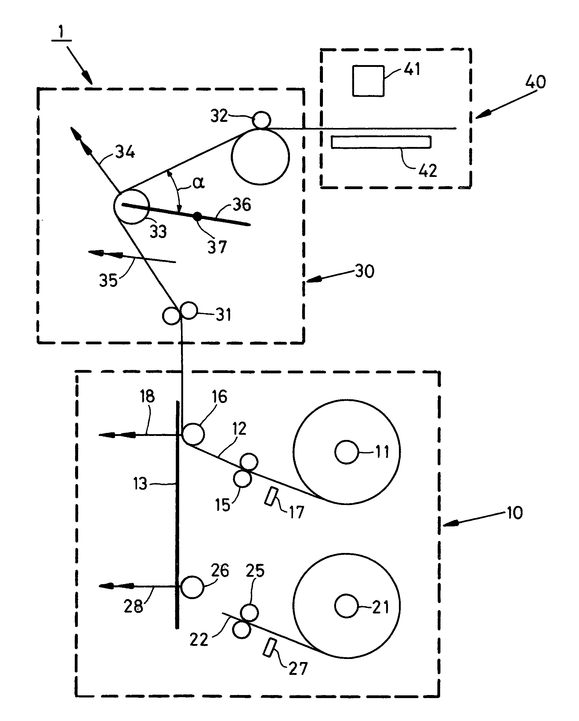
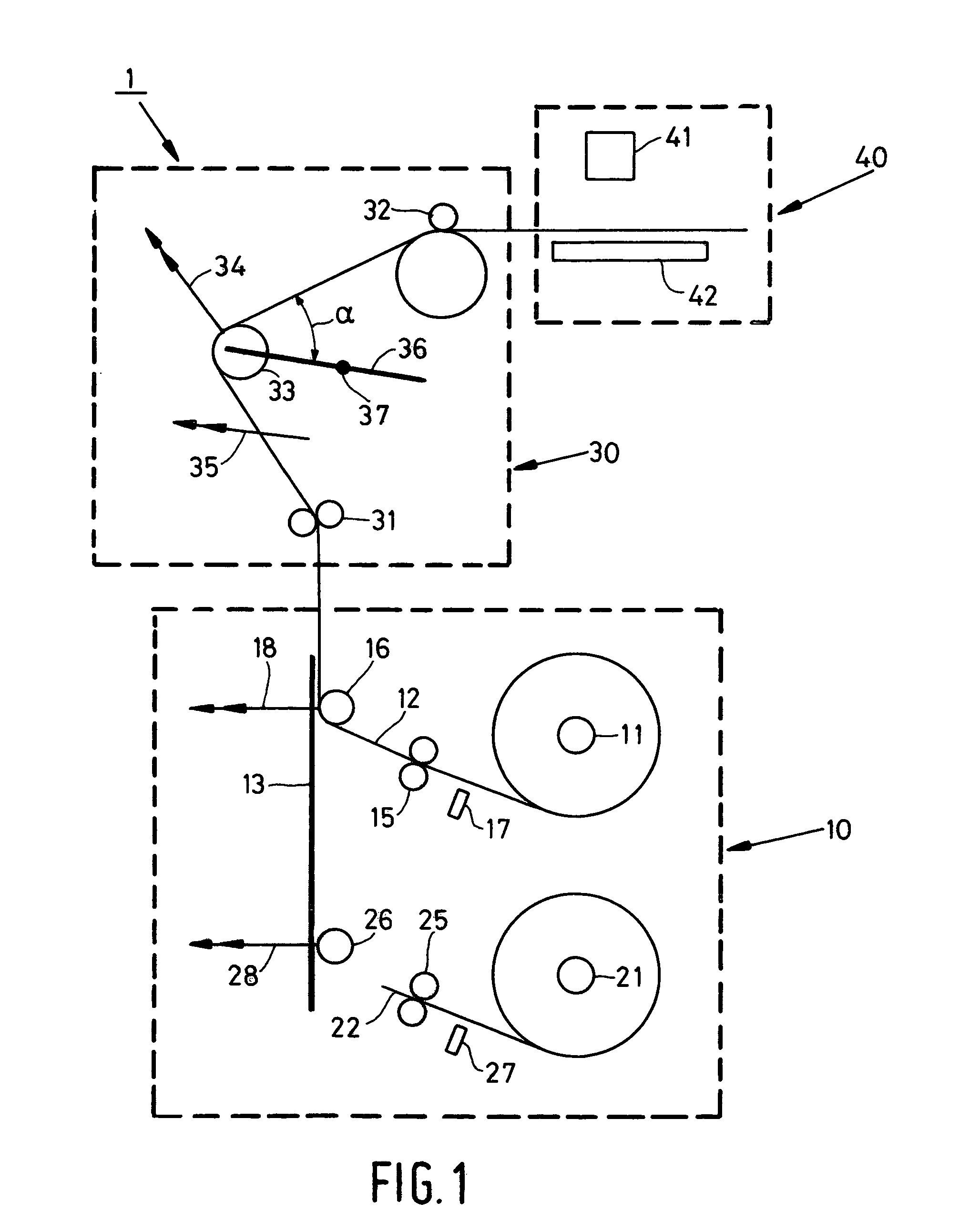
[0020]FIG. 1 is a diagram of a printer according to the present invention. This printer is provided with the supply unit 10, which serves for the storage and delivery of the substrate for printing. In addition, this printer includes a transport unit 30 which transports the substrate from the supply unit 10 to the print engine 40. Unit 30 also provides accurate positioning of the substrate in the print zone formed between the print surface 42 and the inkjet printhead 41. In this embodiment, print engine 40 is a conventional engine which includes printhead 41, which is constructed from a number of separate sub-heads, each of one of the colors: black, cyan, magenta and yellow. Printhead 41 has only a limited printing range so that it is necessary to print the image on the substrate in different sub-images. To this end, the substrate is transported in increments in each case so that a new part of the substrate can be printed in the print zone. In the example illustrated, the substrate 1...


PUM


Abstract

The invention relates to a method of printing a substrate using an inkjet printer which includes a holder to rotatably receive a roll on which the substrate is wound, a downstream print zone and an inkjet printhead for printing the substrate at the print zone, a transport means for engaging and transporting the substrate to the print zone during which transport the substrate is unwound from the roll, and a guide element which is situated downstream of the roll in front of the transport means to guide the substrate from the roll to the transport means, the method including the steps of transporting the substrate over a predetermined distance with control of the transport means, during which transport the guide element is moved from a first position which the guide element occupies prior to the transport, to a second position such that the distance over which the substrate extends between the roll and the transport means is smaller as a result of the movement and after the substrate has been transported over the predetermined distance, printing a strip of the substrate with control of the inkjet printhead, and after printing of the strip, the re-transport of the substrate over a predetermined distance during which the guide element is moved, which transport is followed by printing a following strip of the substrate, wherein the guide element is brought into the first position prior to the re-transport of the substrate.

Description

BACKGROUND OF THE INVENTION[0001]The present invention relates to a method of printing a substrate using an inkjet printer, which printer includes a holder which rotatably receives a roll on which the substrate is wound, a downstream print zone and an inkjet printhead for printing the substrate in the print zone, a transport means for engaging and transporting the substrate to the print zone as the substrate is unwound from the roll, and a guide element which is situated downstream of the roll in front of the transport means to guide the substrate from the roll to the transport means. The printing method includes the steps of transporting the substrate over a predetermined distance with control of the transport means, during which transport the guide element is moved from a first position occupied by said guide element prior to the transport, to a second position such that the distance over which the substrate extends between the roll and the transport means is smaller as a result o...

Claims


Application Information

Patent Timeline
Patent Type & Authority Patents(United States)
IPC IPC(8): B41J2/01B41J11/00B41J11/42B41J15/00B41J15/04B41J15/18B65H23/10
CPCB41J11/0075B41J11/42B41J15/005B41J15/04B41J15/18
Inventor COENEN, JEROEN J. G.GOEREE, BARRY B.
Owner OCE TECH
Why Eureka
Try Eureka