

Tamper resistant weighted rodent and insect bait station
a weighted, rodent technology, applied in the direction of insect catchers and killers, poisons, packaging, etc., can solve the problems of inconvenient methods for securing a base station, rodents to die, etc., and achieve the effect of convenient implementation
- Summary
- Abstract
- Description
- Claims
- Application Information
AI Technical Summary
Benefits of technology
Problems solved by technology
Method used
Image

Examples
Embodiment Construction
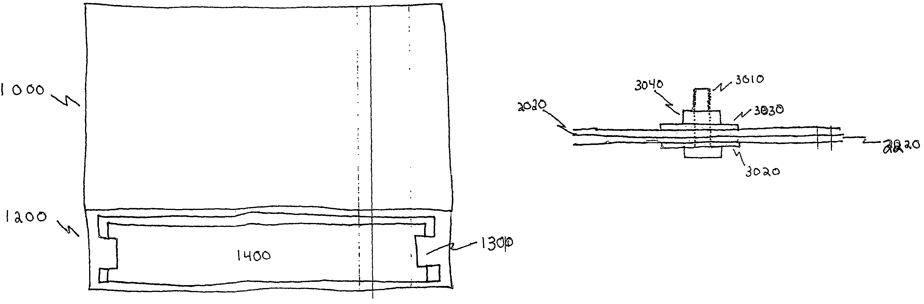
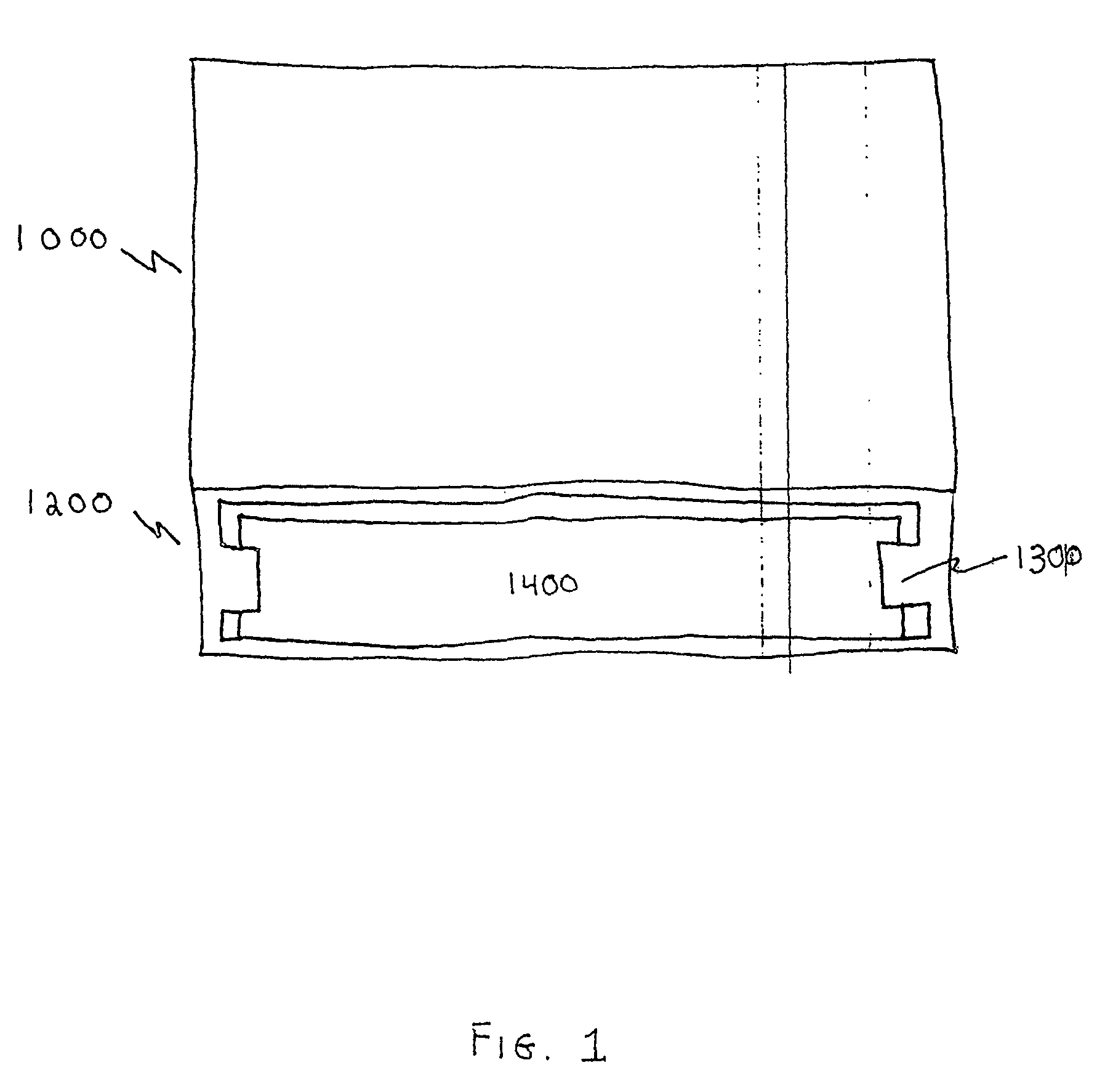
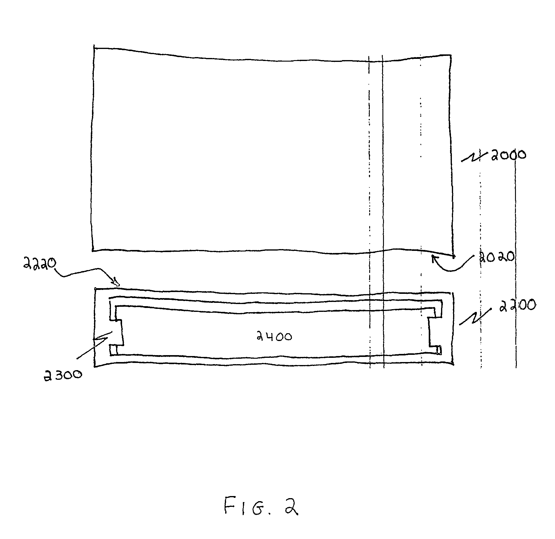
[0016]A preferred embodiment of the present invention is shown in FIG. 1. A conventional enclosure 1000 for a bait station is molded from a suitable plastic material as a unit with a receptacle 1200. Receptacle 1200 is dimensioned to receive a weighting structure 1400, such as an ordinary commercially available patio block that can slide into the receptacle 1200. In this way, no special securing apparatus, such as a nut, bolt, and washer assembly, is required to secure the bait station to the patio block or other weighting structure. Moreover, the patio block can be removed from the bait station by simply removing it from the receptacle 1200, without the necessity of disassembling a separate securing mechanism such as the aforementioned bolt assembly. Further, one or more lip mechanisms 1300 can be provided to secure the weight in place within receptacle 1200. Alternative methods may be employed to secure the weight in place within the receptacle such as described with reference to ...
PUM
 Abstract
Description
Claims
Application Information