Multiple-hearth furnace

a multi-hearth furnace and furnace technology, applied in the field of multi-hearth furnaces, can solve the problems of substantial jerk-free braking, and achieve the effect of convenient cleaning

Inactive Publication Date: 2010-06-15
PAUL WURTH SA
View PDF17 Cites 5 Cited by
  • Summary
  • Abstract
  • Description
  • Claims
  • Application Information

AI Technical Summary

Benefits of technology

[0005]A multiple-hearth furnace according to the present invention comprises, in a manner that is known per se, a furnace wall delimiting a cylindrical space with a vertical axis, a plurality of soles which delimit the hearths within this cylindrical space and at least one rabble arm with a wall scraper. This wall scraper is associated with one of the soles, where it is rotated about the vertical axis of the furnace. During the rotation of this rabble arm about its vertical axis, its wall scraper defines a scraped zone on the inner surface of the furnace wall. According to the present invention, the furnace wall comprises a plurality of wall cavities which form a succession of access openings into the zone scraped by the wall scraper. It will be appreciated that these wall cavities greatly reduce the risk of formation of a crust of hardened material adhering to the inner surface of the furnace wall. Through these access openings in the scraped zone, the wall cavities become filled with material, but a “pasting” compaction effect, which is the origin of the formation of a hardened crust adhering to the inner surface of the furnace wall, scarcely occurs. The material that accumulates in the wall cavities remains relatively soft and results in substantially jerk-free braking.
[0009]The wall cavities can easily be cleaned through the cleaning openings in the external shell by workers equipped with special tools. However, it is also possible to envisage equipping one or more or even all the wall cavities with a fluid injection device so as to be able to eject the material accumulated in the wall cavity onto the sole by means of the liquid injected. Alternatively, one or more or even all of the wall cavities can be equipped with a mechanical pusher, so as to be able to push the material accumulated in a wall cavity onto the sole.

Problems solved by technology

The material that accumulates in the wall cavities remains relatively soft and results in substantially jerk-free braking.

Method used


Image

  • Multiple-hearth furnace
  • Multiple-hearth furnace
  • Multiple-hearth furnace

Examples


Embodiment Construction

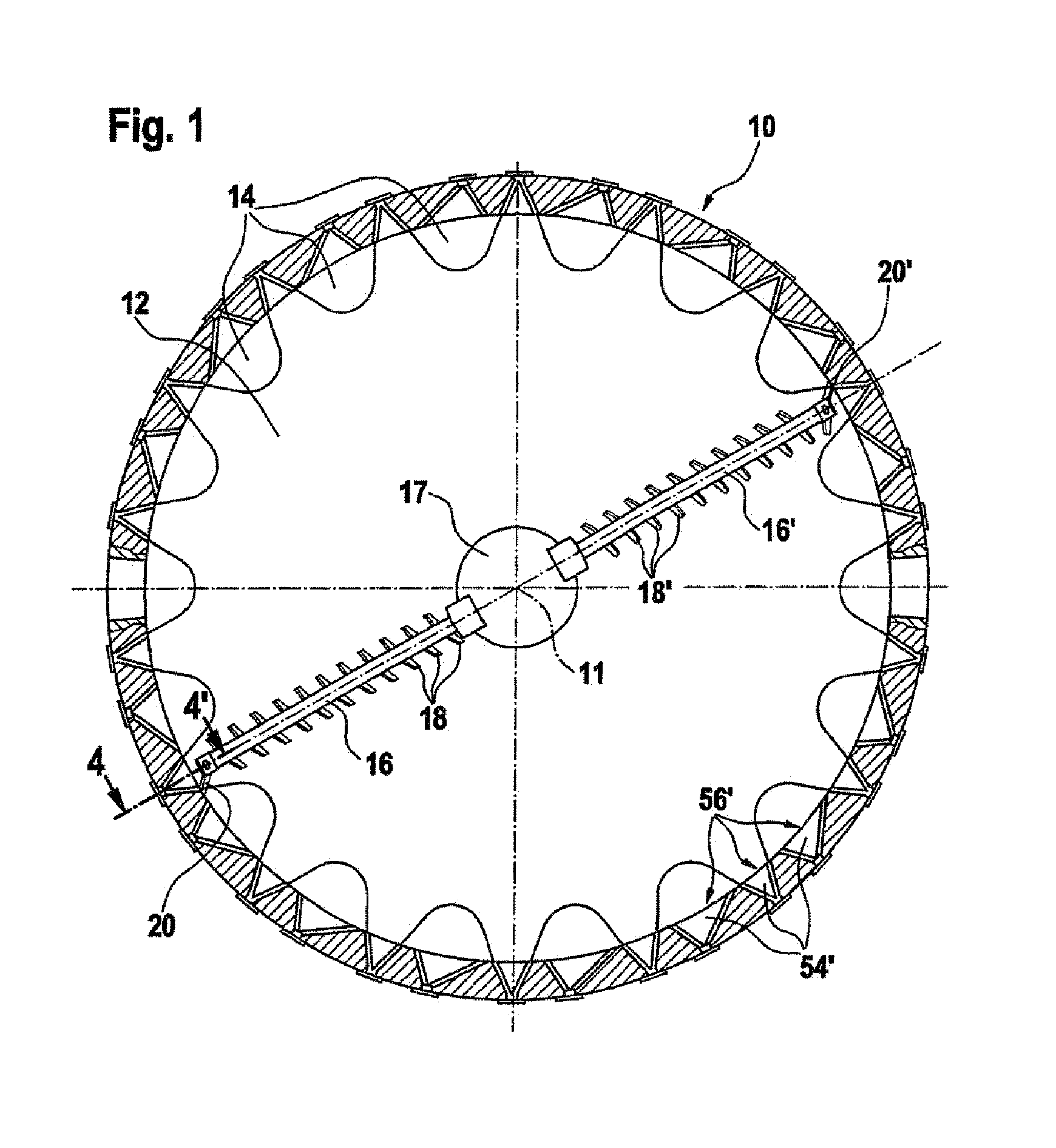
[0018]FIG. 1 shows a first cross section through a multiple-hearth furnace according to the invention. A furnace wall 10 radially delimits a cylindrical space with a vertical axis 11 (perpendicular to the plane of the drawing). Inside this space, a plurality of soles positioned one above the other delimit the stages of the furnace in the vertical direction. FIG. 1 shows a first type of sole 12. This is a sole 12 with peripheral drop holes 14. Associated with this sole 12 are two rabble arms 16, 16′ which are driven in rotation about the vertical axis 11 by a drive shaft 17. Each of the rabble arms 16, 16′ carries a series of sole scrapers 18, 18′ oriented so that they turn over the material under treatment on the sole 12 and displace it toward the periphery of the sole 12, where it falls through the peripheral drop holes 14 onto a peripheral surface of a lower sole. The references 20, 20′ denote wall scrapers, whose function is to recover the material accumulating in the immediate p...


PUM


Abstract

The inventive multi-level furnace comprises a furnace wall delimiting a cylindrical space having a vertical axis, a plurality of beds defining the levels inside said cylindrical space and at least one scraping arm which is provided with a wall scraper and associated with the bed in such a way that it is rotatable about the vertical axis of the furnace. During scraping arm rotation, said wall scraper defines a scraped area on the internal surface of the furnace wall which comprises a plurality of wall cavities forming a row of access openings in the scraped area, thereby making it possible to avoid the formation of a hardened crust adhered to the internal surface of the furnace wall and to develop braking shocks in the scraping arm.

Description

FIELD OF THE INVENTION[0001]The present invention concerns a multiple-hearth furnace.BACKGROUND OF THE INVENTION[0002]A multiple-hearth furnace comprises a furnace wall delimiting a cylindrical space with a vertical axis. A plurality of soles positioned one above the other delimit the hearths of the furnace within this space. In each hearth, rabble arms rotated by means of a central shaft coaxial with the vertical axis of the furnace are provided. These rabble arms are equipped with sole scrapers which turn over the material under treatment on the sole and displace it on a first type of sole toward the periphery and on a second type of sole toward the center of the sole. The first type of sole is provided with peripheral drop holes through which the material under treatment falls onto a sole of the second type in the stage below. The second type of sole is provided with a central drop hole through which the material under treatment falls onto a sole of the first type in the stage be...

Claims


Application Information

Patent Timeline
Patent Type & Authority Patents(United States)
IPC IPC(8): F23B10/00F27B9/18F27D25/00
CPCF27D25/001F27B9/185
Inventor LONARDI, EMILE
Owner PAUL WURTH SA
Why Eureka
Try Eureka