
Sucker rod connection with improved fatigue resistance, formed by applying diametrical interference to reduce axial interference

a diametrical interference and fatigue resistance technology, applied in the direction of hose connection, screw threaded joint, pipe/joint/fitting, etc., can solve the problems affecting the service life of the pin body, and most failures of the rod in the area. , to achieve the effect of increasing the resistance to failur

Active Publication Date: 2010-06-15
SIDERCA I C
View PDF14 Cites 27 Cited by
  • Summary
  • Abstract
  • Description
  • Claims
  • Application Information

AI Technical Summary

Benefits of technology

[0007]To address the problem of rod failure, certain embodiments of this invention are directed to a connection for sucker rods aimed at increasing the resistance to failure caused by fatigue.
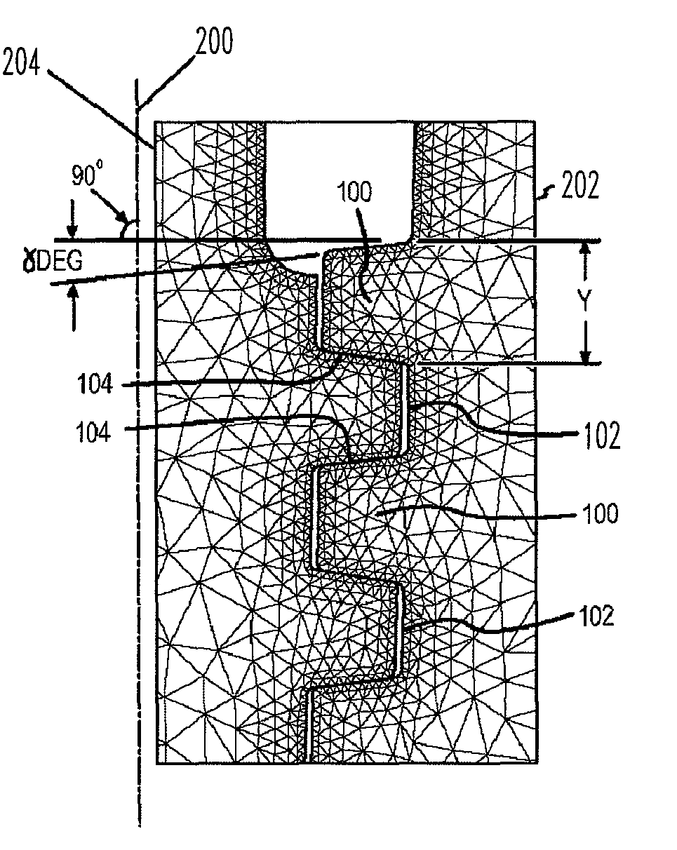
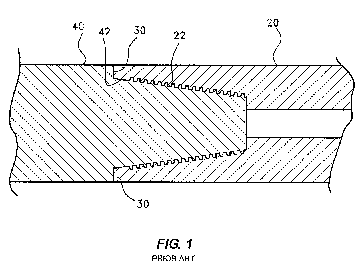
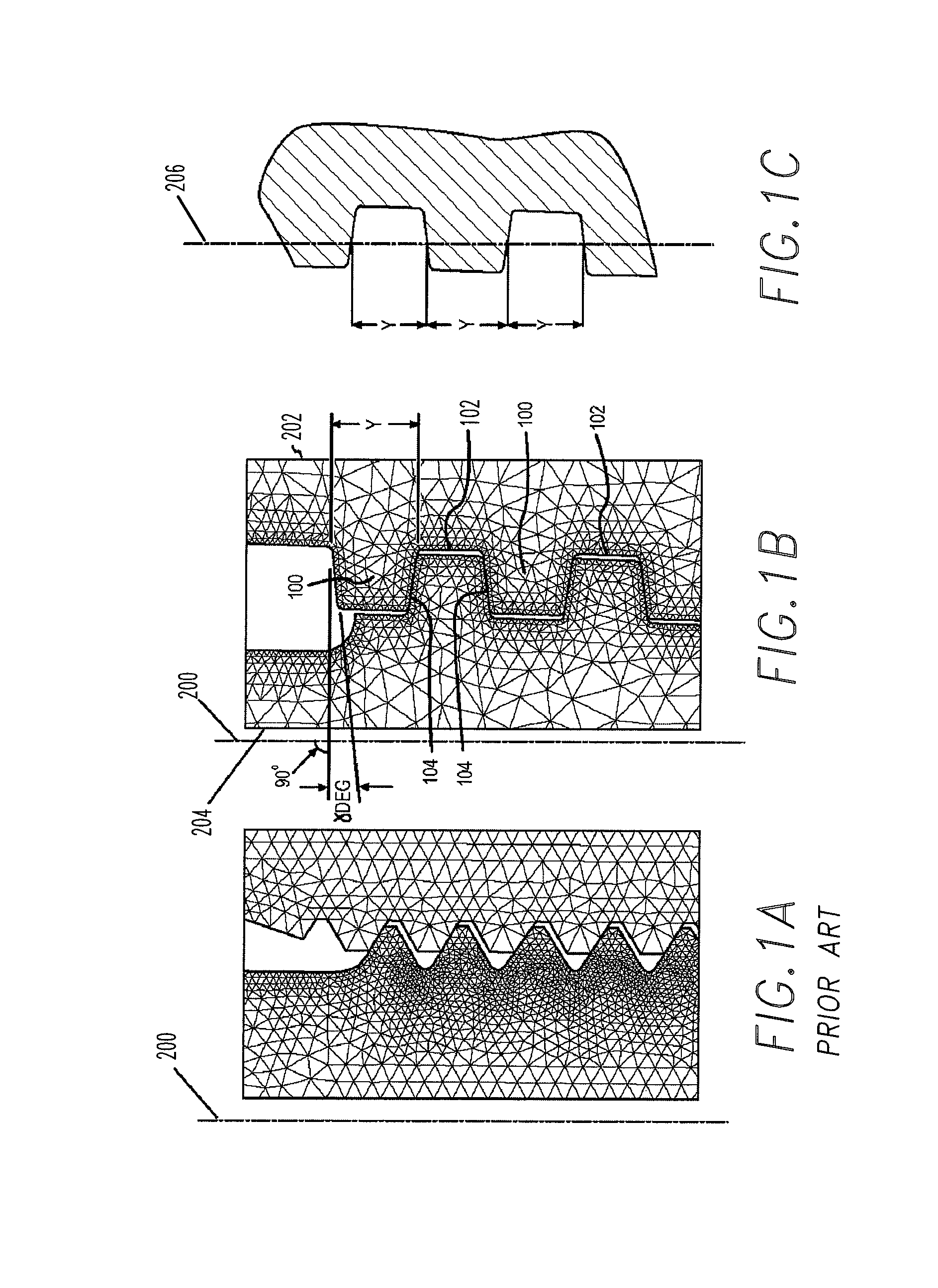
[0008]One embodiment of the present invention relates to a sucker rod connection, preferably comprising a threaded pin at the end of a bar connected to a threaded box, in which fatigue resistance is increased by applying a diametrical interference which prevents disengagement and that substantially reduces axial interference as used in prior designs. More specifically, embodiments of the present invention are directed to a connection that includes a tapered threaded connection, trapezoidal threads and flank-to-flank, load and stab, thread contact. Further embodiments comprise a shoulder close to the last thread of pin, which surface is perpendicular to the pin axis. The box may have another shoulder close to the beginning of the thread, which surface is perpendicular to the box axis. Both surfaces come in contact when making up the connection to accurately control the diametrical interference.

Problems solved by technology

Most failures occur in the rod in the area of the last thread engaged of the pin.
As a result, very often the tension goes above the resistance allowed of the steel and breaks the pin body in the area of the last engaged thread.

Method used


Image

  • Sucker rod connection with improved fatigue resistance, formed by applying diametrical interference to reduce axial interference
  • Sucker rod connection with improved fatigue resistance, formed by applying diametrical interference to reduce axial interference
  • Sucker rod connection with improved fatigue resistance, formed by applying diametrical interference to reduce axial interference

Examples


case 1

[0055]This design is less desirable in two aspects: structural (plasticized threads) and fatigue (coefficient of predominantly negative values). Coefficient D shows poorer behavior in the areas where the maximum principal stress is higher, and such stress is the consequence of axial interference. Thread plasticizing is the result of diametrical interference and 7° flank angle.

case 2

[0056]Our hypothesis that a decrease in axial interference improves stress distribution and, therefore, fatigue coefficient D, is confirmed. However, there is still the problem of threads plasticizing, or thread strain.

case 3

[0057]Although the results obtained in this case—both structural and fatigue-related—are good, the diametrical interference is considered too low because it is near the manufacturer's tolerance level, which is about 0.05 mm per part. Thus, a diametrical interference of 0.05 mm means, in practice, that the diametrical interference may be as great as 0.10 mm or as little as 0.00 mm.


PUM


Abstract

A sucker rod connection is disclosed. The sucker rod connection comprises a tapered male member including a plurality of trapezoidal threads, and, a tapered female member also including a plurality of trapezoidal threads, in which the male member is capable of being received in threaded engagement with the female member, wherein the threads of the male member are in flank-to-flank contact, both flanks on each thread, with the threads of the female member, thereby creating diametrical interference between the male and female members preventing disengagement and substantially reducing axial interference between the male and female members.

Description

CROSS-REFERENCE TO RELATED APPLICATIONS[0001]This application claims priority to U.S. Provisional Application No. 60 / 757,572, filed Jan. 10, 2006, and U.S. Provisional Application No. 60 / 773,523, filed Feb. 15, 2006, both of which are hereby incorporated by reference in their entireties.BACKGROUND OF THE INVENTION[0002]1. Field of the Invention[0003]Embodiments of the present invention relate to a sucker rod connection, and more particularly, a sucker rod connection with improved fatigue resistance and a method for achieving the same.[0004]2. Description of the Related Art[0005]Sucker rods are rods, typically made of steel or other materials, used to make up the mechanical assembly between the surface and downhole components of a rod pumping system. Sucker rods are conventionally about 25 to 30 ft (about 7 to 9 m) long and have threaded pins at ends of an elongate bar to enable the downhole components to be run and retrieved easily. Sucker rods can be connected with a threaded box o...

Claims


Application Information

Patent Timeline
Patent Type & Authority Patents(United States)
IPC IPC(8): F16L25/00
CPCF16L15/006
Inventor TOSCANO, RITA GENOVEVADI TORO, NICOLAS HECTOR MARIO
Owner SIDERCA I C
Learn More