
Tactile feedback device

a feedback device and tactile technology, applied in repeater circuits, frequency-division multiplexes, instruments, etc., can solve the problems of many constraints on displacement and force, insufficient implementation of tactile sensation, etc., and achieve the effect of improving controllability and being easy to miniaturiz

Active Publication Date: 2010-06-15
KOREA ADVANCED INST OF SCI & TECH
View PDF6 Cites 33 Cited by
  • Summary
  • Abstract
  • Description
  • Claims
  • Application Information

AI Technical Summary

Benefits of technology

[0009]Another object of the present invention is to provide a tactile feedback device that can be easily miniaturized and improve controllability.
[0010]Still another object of the present invention is to provide a low-power and high-output tactile feedback device.

Problems solved by technology

However in the tactile feedback device of the aforementioned patent document, since the blade of the tactile sensation modification components is manufactured into a large area due to its mechanical structure, the intervals of the points stimulating the skin are far apart, so the problem is that it is insufficient for implementing the tactile sensation.
Also, it has a disadvantage that there are many constraints to implementable displacement and force because the coil of the electromagnetic device is of a flat plate type as well as the blade of the tactile sensation modification components is supported on the touch plate by arms.

Method used


Image

  • Tactile feedback device
  • Tactile feedback device
  • Tactile feedback device

Examples


Embodiment Construction

[0021]Below will be described a tactile feedback device according to preferred embodiments of the present invention in detail with reference to the accompanying drawings.

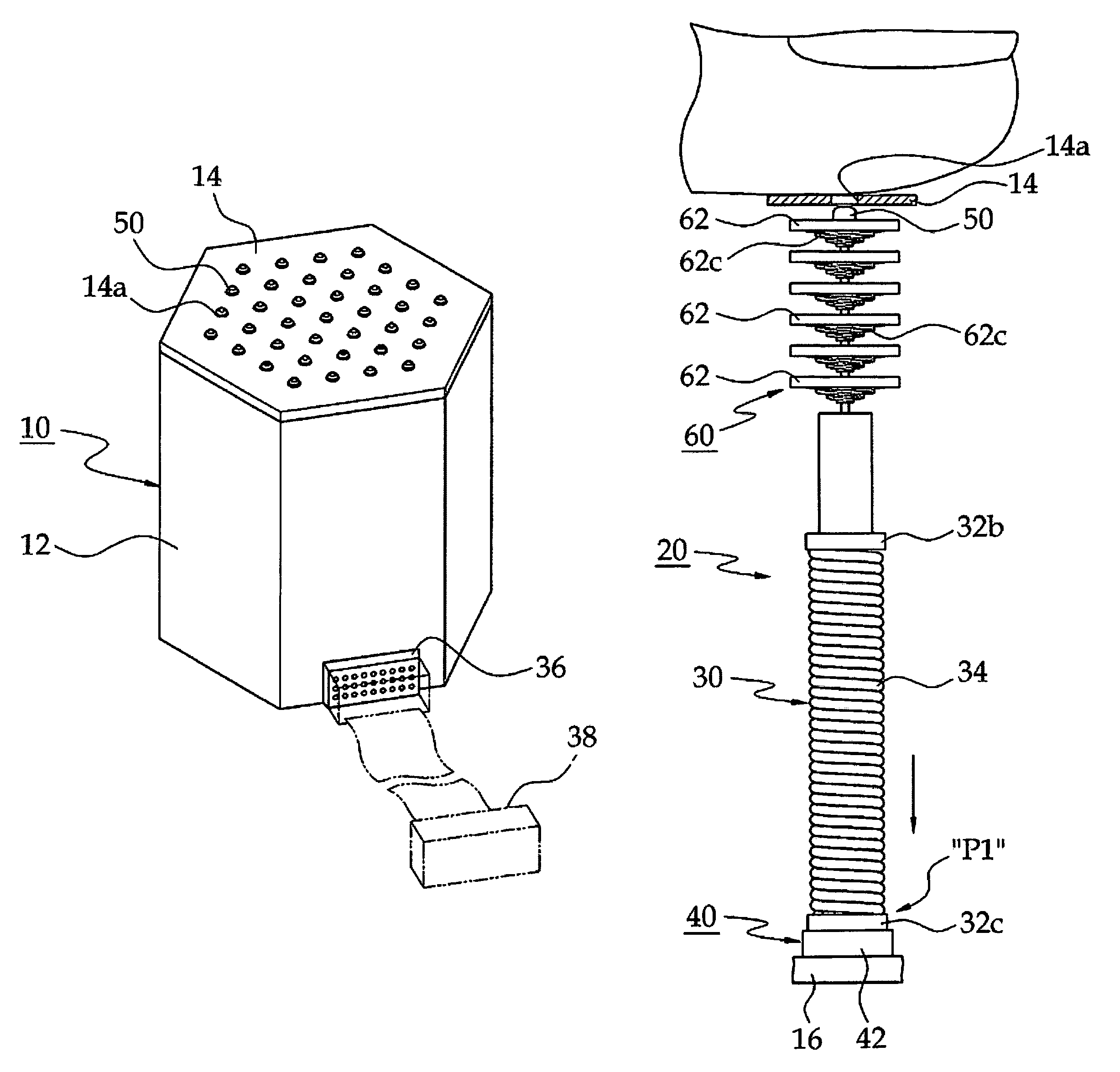
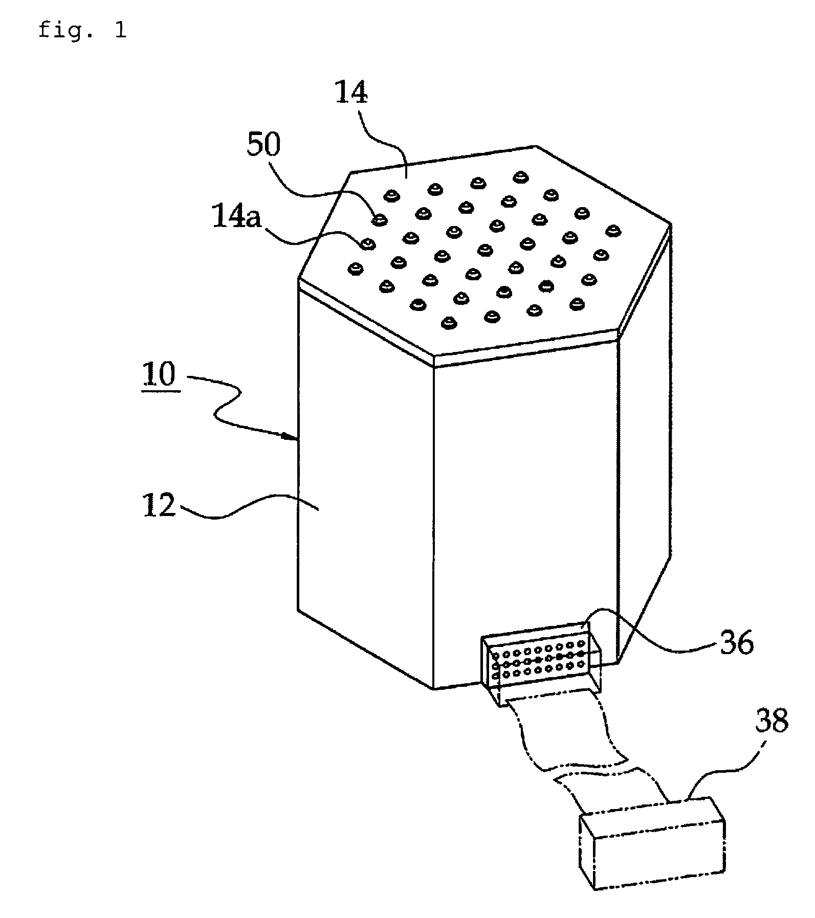
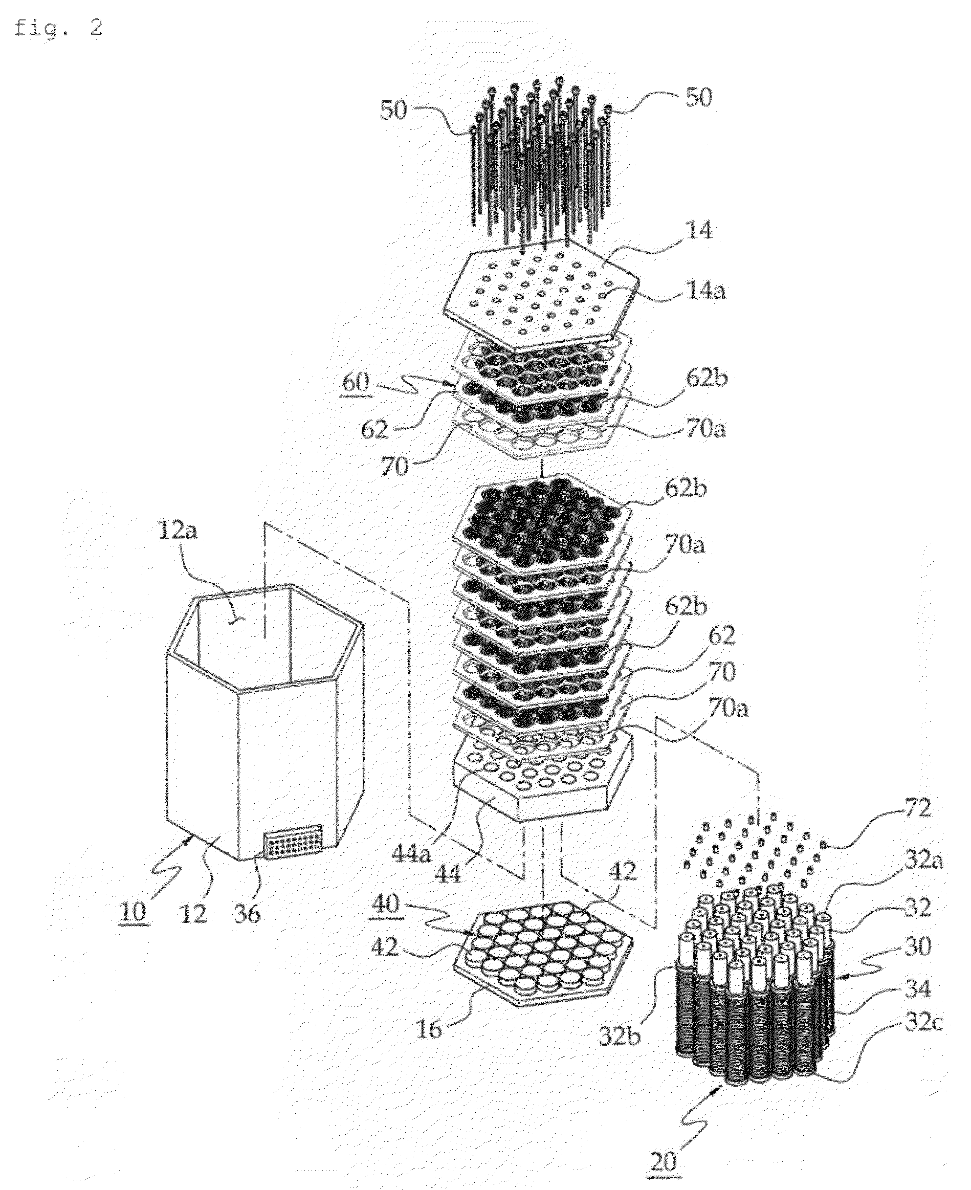
[0022]First, referring to FIG. 1 and FIG. 2, the tactile feedback device of the present invention has a housing 10 configuring the overall shape. The housing 10 comprises a body 12, a first cover 14, and a second cover 16. The transverse section of the body 12 is formed in a hexagon having a hollow space 12a and has opposite opened portions at top and bottom ends. The skin of the user, for example, his or her hand and / or finger, gets close to one end of the housing 10. For the transverse section of the body 12, the one formed in a hexagon is illustrated and described, but this is only illustrative, and it may be formed in various shapes such as a polygon, ellipse or circle. The first and second covers 14 and 16 are mounted on opposite ends of the body 12 so as to close the space 12a. The first cover 14 has a plurali...


PUM


Abstract

The present invention discloses a tactile feedback device for giving realistic touch sensation to the user by stimulating the skin of the user. The tactile feedback device of the present invention comprises a housing having one end positioned near the skin of the user in use, an actuator, touch pins and an elastic means. The actuator is mounted inside the housing to convert electromagnetic energy into kinetic energy. The touch pins are mounted inside the housing so as to pop in and out, and the front end thereof is popped out of one end of the housing to contact the skin, and is connected with the actuator so as to be operated by kinetic energy of the actuator. The elastic plates of the elastic means are mounted between one end of the housing and the actuator, and have the touch pins fixedly passing through so as to be interlocked with the touch pins, and when the touch pins pop in and out, they are elastically deformed to have elastic energy. According to the present invention, the touch pins stimulate the skin of the user by dint of an interlocking structure of the actuator that converts electromagnetic energy into kinetic energy and the elastic means, so it is possible to implement realistic touch sensation.

Description

[0001]This application claims priority to Korean Patent Application No. 10-2007-0066393, filed on Jul. 3, 2007, in the Korean Intellectual Property Office, the entire contents of which are hereby incorporated by reference.BACKGROUND OF THE INVENTION[0002]1. Field of the Invention[0003]The present invention relates to a tactile feedback device, more specifically to a tactile feedback device for giving realistic feeling sensation to the user by stimulating the skin of the user.[0004]2. Description of the Related Art[0005]A haptic device has utilized in various fields such as virtual reality, simulation, wearable computers, robotics and medical use, and it is also called haptic interface. The haptic device is classified into a force feedback device for transmitting physical force to the muscles and joints and a tactile feedback device for transmitting skin stimulation such as texture, temperature, pressure, vibration and pain through mechanoreceptors that are in contact with the skin. ...

Claims


Application Information

Patent Timeline
Patent Type & Authority Patents(United States)
IPC IPC(8): H04B3/36
CPCG06F3/016G06F3/00G06F3/02
Inventor YANG, TAE-HEONKWON, DONG-SOOLEE, SEUNG-SEOBYUK, NAM-SU
Owner KOREA ADVANCED INST OF SCI & TECH
Learn More