Electric power-feeding structure

a technology of electric power and structure, applied in the direction of wing accessories, cable arrangements between relatively moving parts, electric devices, etc., to achieve the effect of simplifying the electric power-feeding structure, reducing the looseness of electrical wires, and small looseness produced therein

Active Publication Date: 2010-06-22
YAZAKI CORP
View PDF11 Cites 5 Cited by
  • Summary
  • Abstract
  • Description
  • Claims
  • Application Information

AI Technical Summary

Benefits of technology

[0015]In the electric power-feeding structure in accordance with the invention, the electrical wire is routed alongside the arm which drives the raising or lowering of the moving body, so that a major portion of the electrical wire which follows the raising and lowering of the moving body can be restricted by the arm. Further, in the vicinity of the rotating shaft of the arm, which is a movable portion, the electrical wire is routed in such a manner as to be capable of undergoing flexural deformation, thereby allowing the electrical wire to follow the raising or lowering of the moving body. In the electrical wire which is routed in the vicinity of the rotating shaft of the arm, looseness can occur in conjunction with the raising or lowering of the moving body. However, the stroke of the peripheral portion of the rotating shaft of the arm is smaller than the stroke of the moving body, and an excess length required for the electrical wire which is routed in that portion can be small, so that the looseness produced therein can also be made small. Furthermore, the fixing portion of the electrical wire on the base is provided on the straight line L1 defined by the rotating shaft of the arm and the fixing portion of the electrical wire on the arm when the arm is at the intermediate position of its swinging range, and the bend of the electrical wire accompanying the swinging motion of the arm is made uniform with the straight line located therebetween. Accordingly, the looseness of the electrical wire can be reduced further. Hence, a member for restricting the movement of the electrical wire, such as a case for accommodating the electrical wire, is not separately required, so that it is possible to miniaturize and simplify the electric power-feeding structure.

Problems solved by technology

Looseness is produced in the feeding line in conjunction with the raising or lowering of the window glass 102, and in a case where the amount of looseness is large and if such a feeding line is able to move without any restriction, there is a possibility of causing a malfunction such as the feeding line becoming bitten by a raising and lowering mechanism of the window glass 102.

Method used


Image

  • Electric power-feeding structure
  • Electric power-feeding structure
  • Electric power-feeding structure

Examples


Embodiment Construction

[0024]Referring now to the accompanying drawings, a description will be given of a preferred embodiment of an electric power-feeding structure in accordance with the invention.

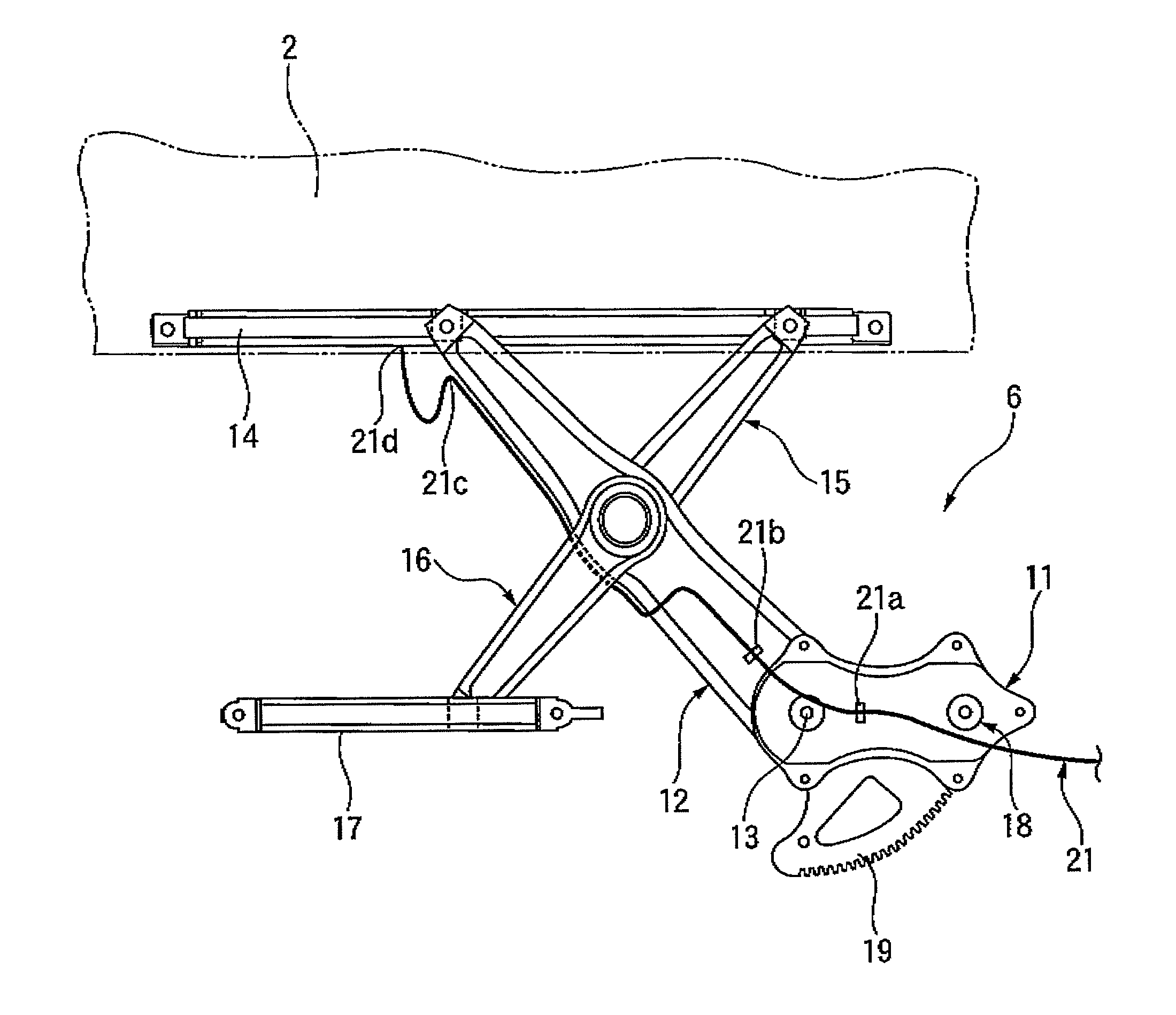
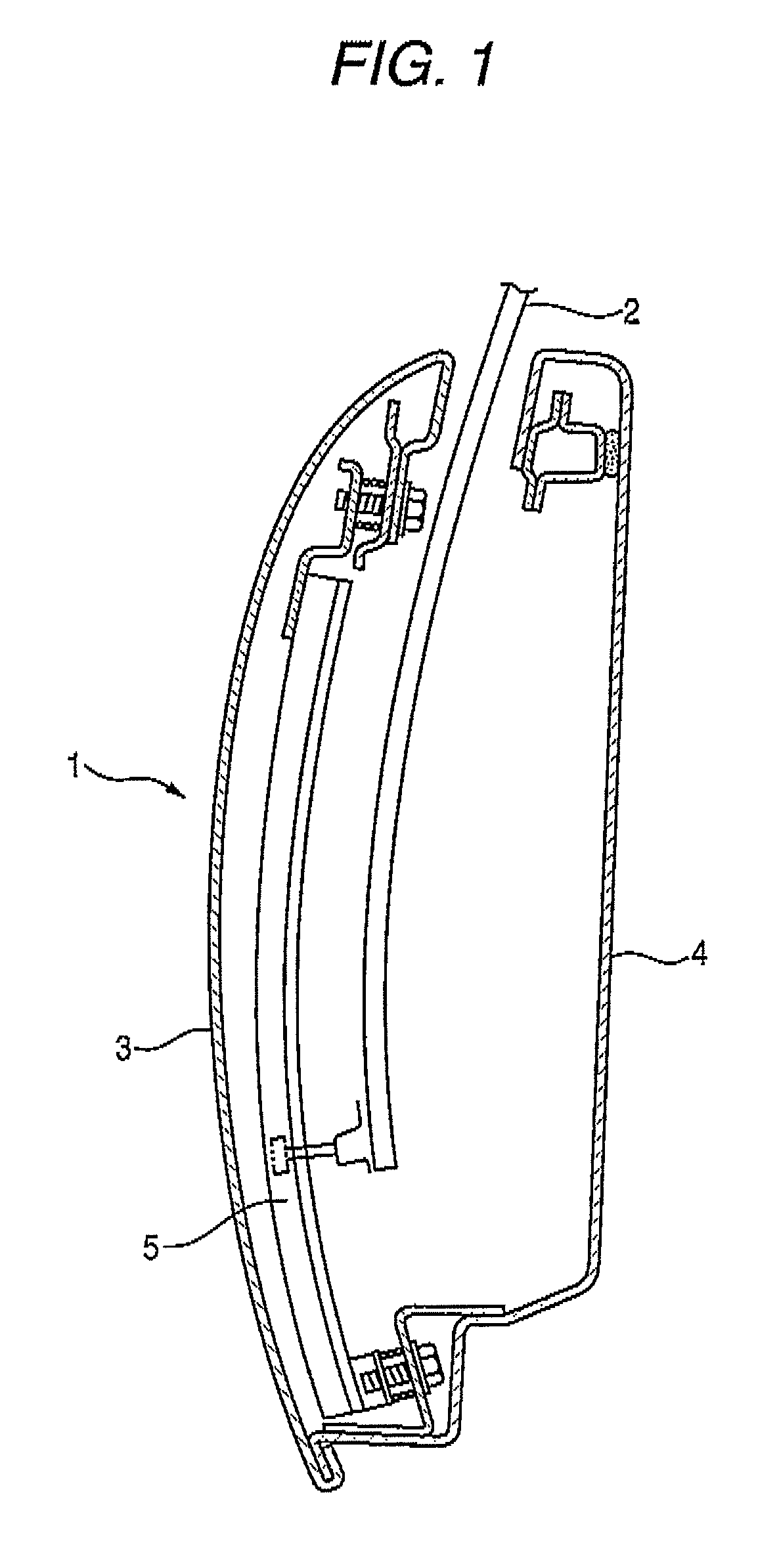
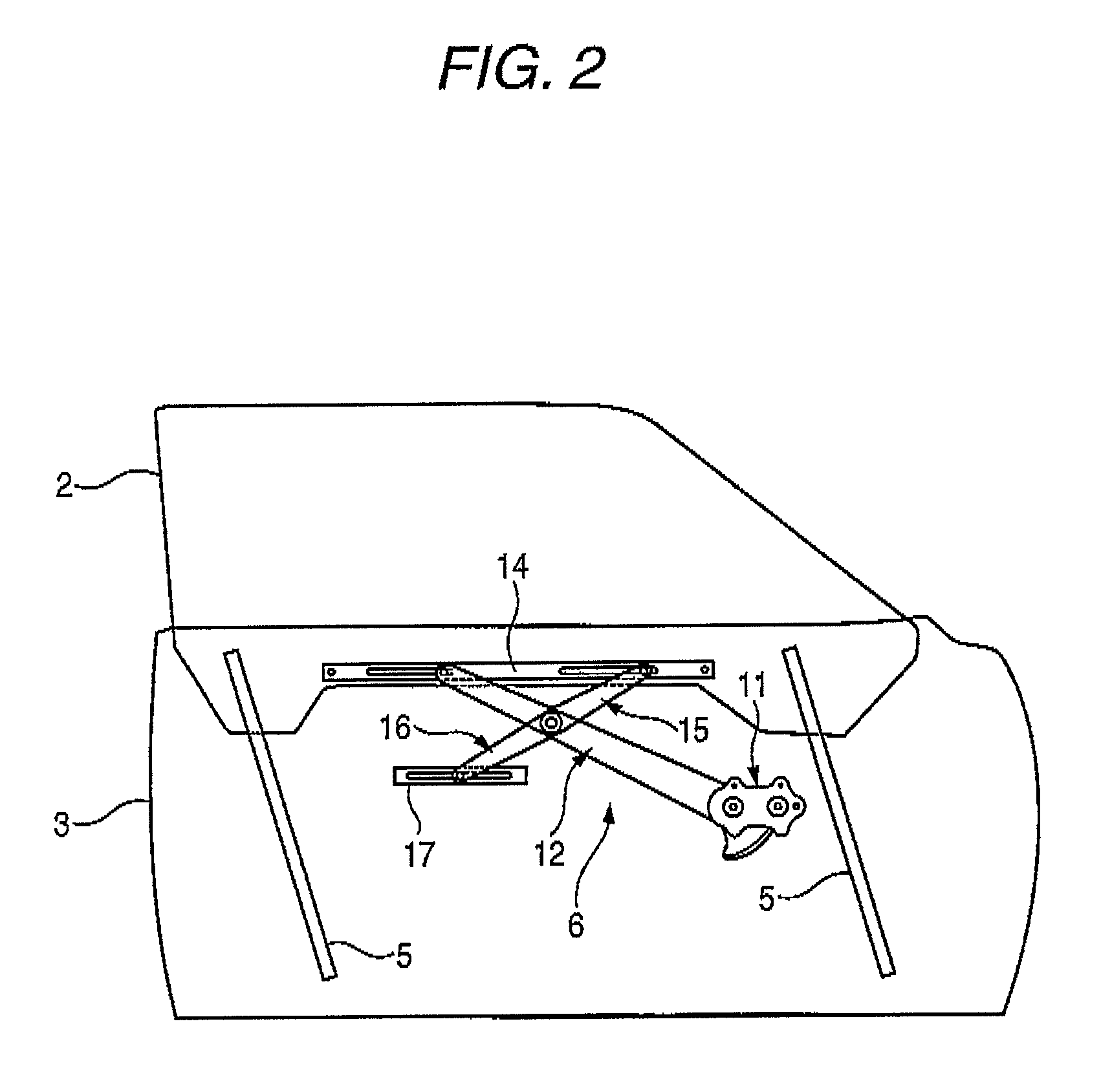
[0025]FIG. 1 is a cross-sectional view of a door of an automobile to which the electric power-feeding structure in accordance with the invention is applied. FIG. 2 is a front elevational view illustrating a raising and lowering mechanism of a window glass of the door shown in FIG. 1. FIG. 3 is a detailed front elevational view of the raising and lowering mechanism shown in FIG. 2 and illustrates an embodiment of the electric power-feeding structure in accordance with the invention. FIG. 4 is a plan view of the raising and lowering mechanism shown in FIG. 3. FIGS. 5A to 5C are front elevational views illustrating the operation of the electric power-feeding structure shown in FIG. 3 in conjunction with the raising or lowering of the window glass. FIG. 6 is a front elevational view illustrating the operation of a...


PUM


Abstract

An electric power-feeding structure for feeding electric power to a moving body which is driven to be raised or lowered, includes: an arm having a distal end connected to the moving body movably in a horizontal direction and a proximal end rotatably driven to swing, to thereby drive the raising or lowering of the moving body. An electrical wire is routed alongside the arm, and one end of the electrical wire extending from the distal end is connected to the moving body. In a vicinity of a rotating shaft of the arm, the electrical wire is fixed to the arm at a first fixing point and to a base for supporting the arm at a second fixing point. The first fixing point is provided on a straight line defined by the rotating shaft and the second fixing point when the arm is at an intermediate position of its swinging range.

Description

BACKGROUND OF THE INVENTION[0001]1. Technical Field[0002]The present invention relates to an electric power-feeding structure for feeding electric power to a moving body which is driven to be raised or lowered, such as a window glass of a motor vehicle.[0003]2. Background Art[0004]In the window glass of a motor vehicle, such as an automobile, electric power is fed to the window glass in which a heating wire is laid for such as the prevention of dew condensation. As an electric power-feeding structure for feeding electric power to the window glass in cases such as where the heating wire is laid in the window glass which is driven to be raised or lowered, an electric power-feeding structure shown in FIGS. 7A and 7B is conventionally known.[0005]In the electric power-feeding structure shown in FIGS. 7A and 7B, a moving body-side connector 105 provided on a window glass 102 which is disposed in an inner space of a door 101 and is driven to be raised or lowered, and a door-side connector...

Claims


Application Information

Patent Timeline
Patent Type & Authority Patents(United States)
IPC IPC(8): E05F11/44
CPCH02G11/00B60R16/0215
Inventor SUZUKI, KAORUYAMAGUCHI, ATSUYOSHIUEHARA, TAKEHIKO
Owner YAZAKI CORP
Why Eureka
Try Eureka