Molding device for molding a weather strip

a molding device and weather strip technology, applied in the direction of dough shaping, manufacturing tools, applications, etc., can solve the problems of degradation of the appearance of the end of the extruded portion, and achieve the effects of reducing the transfer of heat of the molding device, and reducing the temperature of the surfa

Inactive Publication Date: 2010-06-22
TOYODA GOSEI CO LTD
View PDF5 Cites 6 Cited by
  • Summary
  • Abstract
  • Description
  • Claims
  • Application Information

AI Technical Summary

Benefits of technology

[0021]In the invention, a molding device is provided with a holding portion for clamping the end of the extruded portion, and the cavity for forming the molded portion, the holding portion has a holding core to come in contact with the end of the extruded portion, and a thermal conduction diminishing portion to diminish thermal conduction within the molding device. More specifically, a part of the thermal conduction diminishing portion is formed by a material with a low thermal conductivity. This can reduce the transfer of heat of the molding device to the end of the extruded portion, which can reduce the indent depth left in the surface due to heat reforming of the end. Therefore, it is possible to make favorable the appearance of the end of the extruded portion.
[0056]In accordance with the present invention, the holding portion of the molding device has the holding core to come in contact with the end of the extruded portion, and at least a part of the holding core includes a cooling hole for cooling the holding core formed in the inside thereof, such that a refrigerant is circulated through the cooling hole. With this configuration, it is possible to reduce the temperature of the surface of the holding core to come in contact with the end of the extruded portion. This can almost eliminate the depression left in the surface of the end. Thus, it is possible to make favorable the appearance of the end of the extruded portion.

Problems solved by technology

This unfavorably causes a problem of degradation of appearance of the end of the extruded portion 117 of the door weather strip 110.

Method used


Image

  • Molding device for molding a weather strip
  • Molding device for molding a weather strip
  • Molding device for molding a weather strip

Examples


first embodiment

[0088]A method for manufacturing the door weather strip 10, and the molding device 20 therefor according to the first embodiment will be described.

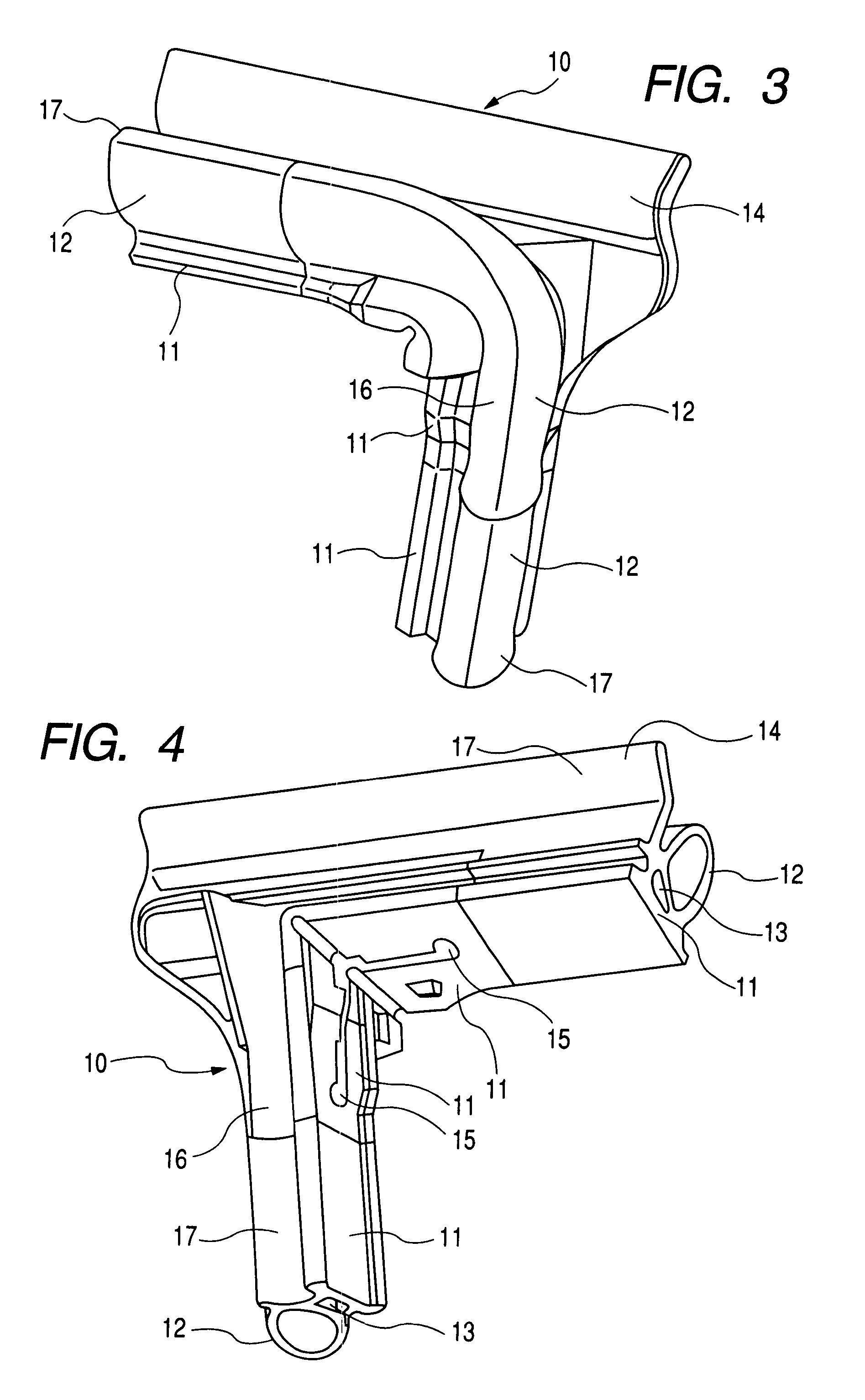
[0089]The door weather strip 10 manufactured in accordance with the invention includes, as shown in FIGS. 3 and 4, the extruded portions 17 formed by extrusion, and the molded portion 16 molded by using the molding device 20. The extruded portions 17 include two types of the portion to be attached to the upper side of the door, and the portion to be attached to the longitudinal side, which are different in cross sectional shape from each other. The respective ends of the two pieces of the extruded portions 17 and the molded portion 16 to be attached to the corner portion of the door frame are integrally connected to one another.

[0090]First, a description will be given to a method for manufacturing the portion of the molded portion 16 to be connected with the extruded portion 17 to be attached to the longitudinal side of the door frame, an...

second embodiment

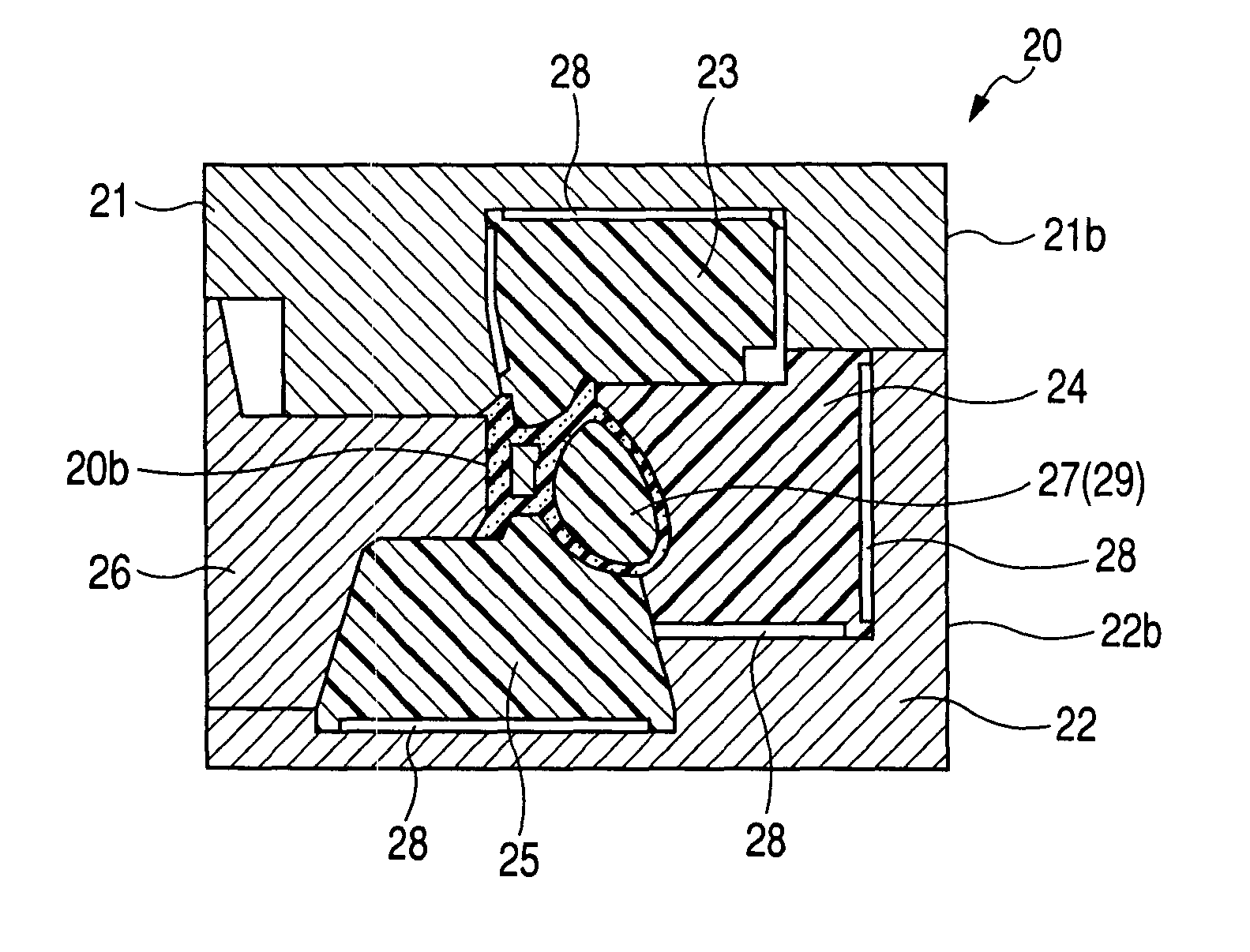
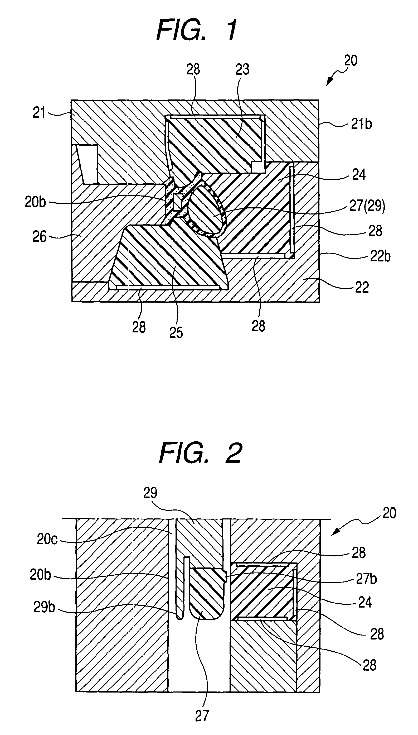
[0116]A molding device 20 for manufacturing the door weather strip 10 according to the second embodiment will be described. The molding device 20 has basically a similar structure to the molding device 20 according to the first embodiment.

[0117]In the second embodiment, the first holding core 23, the second holding core 24, and the third holding core 25 include cooling holes 23c, 24c, and 25c, formed in their respective insides so as to allow a refrigerant to circulate therein. The cooling holes 23c, 24c, and 25c will be described by taking the cooling hole 24c as an example.

[0118]As for the cooling holes 24, as shown in FIGS. 7 and 8, two cooling holes 24c are provided inside the second holding core 24. The tips of the two cooling holes 24c in the second holding core 24 are connected so that the holes are continuous to each other as shown in FIG. 2. The other tips of the two cooling holes 24c are connected to a cooling hole of a cooling unit (not shown) formed outside of the moldin...

third embodiment

[0133]A description will be given to a manufacturing method for molding the corner portion of the glass run 50, and the molding device 30 according to the third embodiment by reference to FIG. 10. The glass run 50 includes, as with the door weather strip 10, an extruded portion formed by extrusion, and a molded portion molded by using the molding device 30.

[0134]The extruded portion of the glass run 50 is provided with a glass run body, U-shaped in cross section, including a vehicle exterior side sidewall 51, a vehicle interior side sidewall 52, and a bottom wall 53 connecting the vehicle exterior side sidewall 51 and the vehicle interior side sidewall 52, U-shaped in cross section, a vehicle exterior side seal lip 54 and a vehicle interior side seal lip 55 obliquely extending from their respective tips of the vehicle exterior side sidewall 51 and the vehicle interior side sidewall 52 toward the inside of the glass run body, and a vehicle exterior side cover lip 56 and a vehicle int...


PUM

PropertyMeasurementUnit
thicknessaaaaaaaaaa
thermal conductivityaaaaaaaaaa
heataaaaaaaaaa

Abstract

A molding device is provided with a holding portion for clamping the end of an extruded portion, and a cavity for forming a molded portion. The holding portion has holding cores to come in contact with the end of the extruded portion, and at least a part of the holding cores is formed by a material with a low thermal conductivity. Thus, the molding method of a weather strip includes, clamping the end of the extruded portion by the holding portions, then, ejecting or injecting a rubber material for molding the molded portion in the cavity, and then, molding the rubber by vulcanization.

Description

BACKGROUND OF THE INVENTION[0001]1. Field of the Invention[0002]The present invention relates to a molding method of a weather strip in which a molded portion is molded at an end of an extruded portion of the weather strip, and the extruded portion is formed by extrusion, and a mold for molding the molded portion.[0003]2. Related Art[0004]A seal between a door of an automobile and a peripheral part of a body opening is accomplished by a door weather strip attached to an outer part of a door frame provided at an outer peripheral portion of the door, and / or an opening weather strip attached at a flange of the peripheral part of the body opening. Incidentally, a seal between a door glass and the door is accomplished by a glass run attached to a channel at an inner part of the door frame.[0005]As shown in FIG. 15, a door weather strip 110 is formed along a door frame (not shown), and includes extruded portions 117, linearly formed by extrusion, which are portions to be attached to an up...

Claims


Application Information

Patent Timeline
Patent Type & Authority Patents(United States)
IPC IPC(8): B29C45/14
CPCB29C33/3828B29C45/14409B29L2031/265
Inventor KUBO, YOSHIHISA
Owner TOYODA GOSEI CO LTD
Why Eureka
Try Eureka