Hydraulic control apparatus and hydraulic control method for automatic transmission

a technology of hydraulic control apparatus and automatic transmission, which is applied in the direction of instruments, transportation and packaging, and engines may race, and the gear suitable for the vehicle speed may not be established, so as to achieve the effect of suppressing the shift shock

Inactive Publication Date: 2010-06-22
TOYOTA JIDOSHA KK
View PDF15 Cites 7 Cited by
  • Summary
  • Abstract
  • Description
  • Claims
  • Application Information

AI Technical Summary

Benefits of technology

[0018]This invention provides a hydraulic control apparatus and control method for an automatic transmission, which suppresses shift shock when the transmission shifted while the vehicle speed is decreasing.

Problems solved by technology

However, depending on the type of downshift, when this skip shift is performed, the release and apply timing of the friction apply elements (i.e., clutches and brakes) of the automatic transmission may be off (i.e., an apply operation or the like may end up being performed before the torque capacity is obtained in the apply-side friction apply element), and as a result, the engine may race and there may be a loss of torque, and shift shock may result.
However, in transmissions that perform this kind of sequential shifting, there is a possibility that the gear suitable for the vehicle speed may not be able to be established in cases such as when the vehicle is decelerating relatively quickly, for example, because the total shift time increases.
As a result, a phenomenon similar to that of a so-called power-on downshift may occur which produces shift shock that pulls the vehicle forward.
In this way, the sequential shifting of the related art leads to a delay of a shift operation into the appropriate gear, as well as a deterioration in drivability from shift shock.
These kinds of problems become more evident as the number of gears (i.e., speeds) in automatic transmissions increases.
In particular, automatic transmissions in recent years are being made to have more and more gears (i.e., speeds), which makes them increasingly susceptible to these kinds of problems.
Even if an automatic transmission shifts into a lower gear in response to an operation of the shift lever while the vehicle is decelerating (i.e., even if there is a downshift operation in the sequential mode), the foregoing problems when the gear appropriate for the vehicle speed is unable to be established may still occur, just as described above.
That is, those problems may also occur with the shift timing (i.e., the timing at which there is a shift demand when a shift operation is not being performed) when the vehicle is in the power-off state (i.e., when the engine is being driven by the driving wheels) and the vehicle is decelerating relatively rapidly.

Method used


Image

  • Hydraulic control apparatus and hydraulic control method for automatic transmission
  • Hydraulic control apparatus and hydraulic control method for automatic transmission
  • Hydraulic control apparatus and hydraulic control method for automatic transmission

Examples


Embodiment Construction

[0059]In the following description and the accompanying drawings, the present invention will be described in more detail in terms of example embodiments. In the following description, the powertrain and the basic operation and the like of the automatic transmission of the vehicle will first be described, after which power-off downshift control, which is the characteristic control of the example embodiments, will be described.

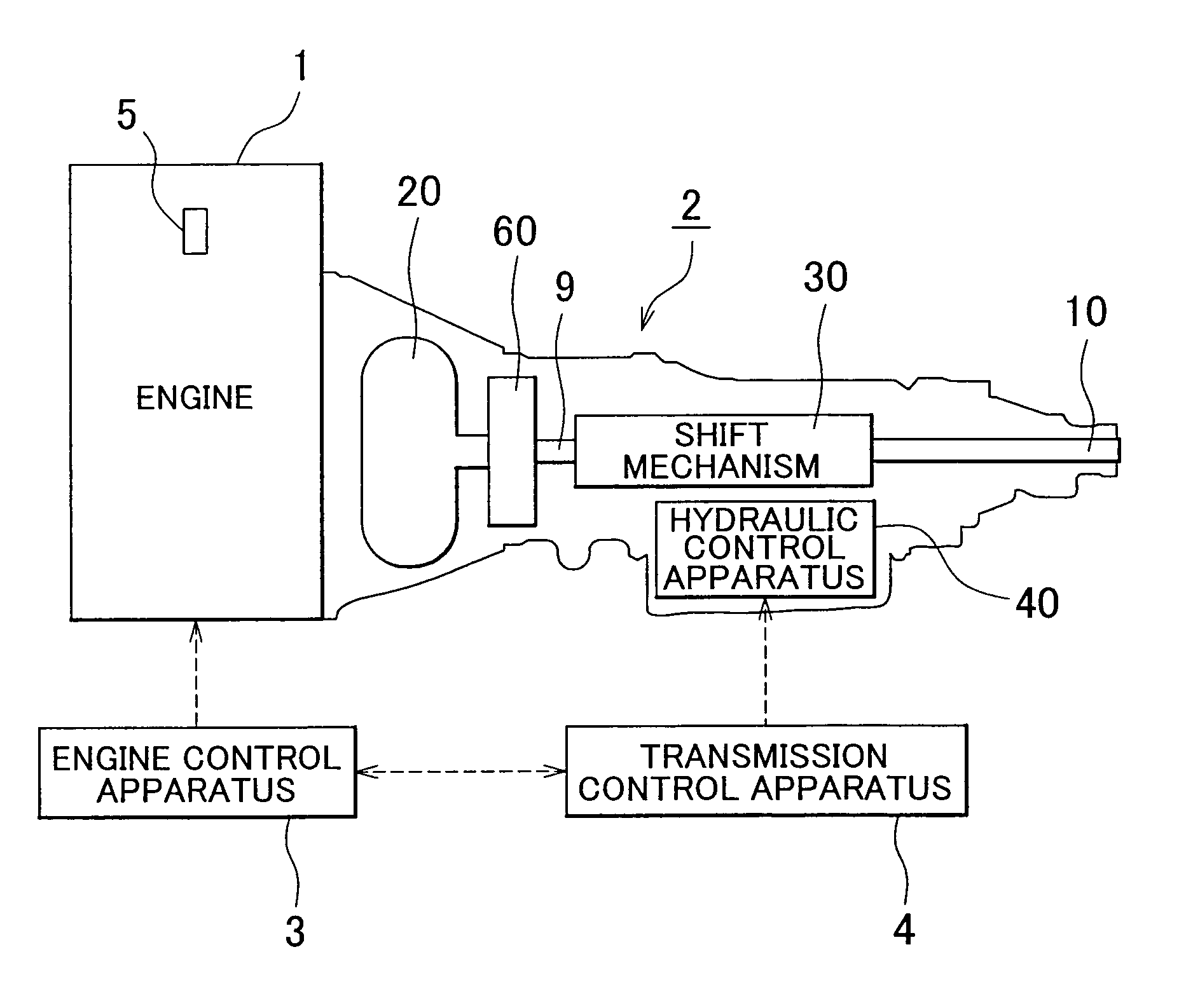
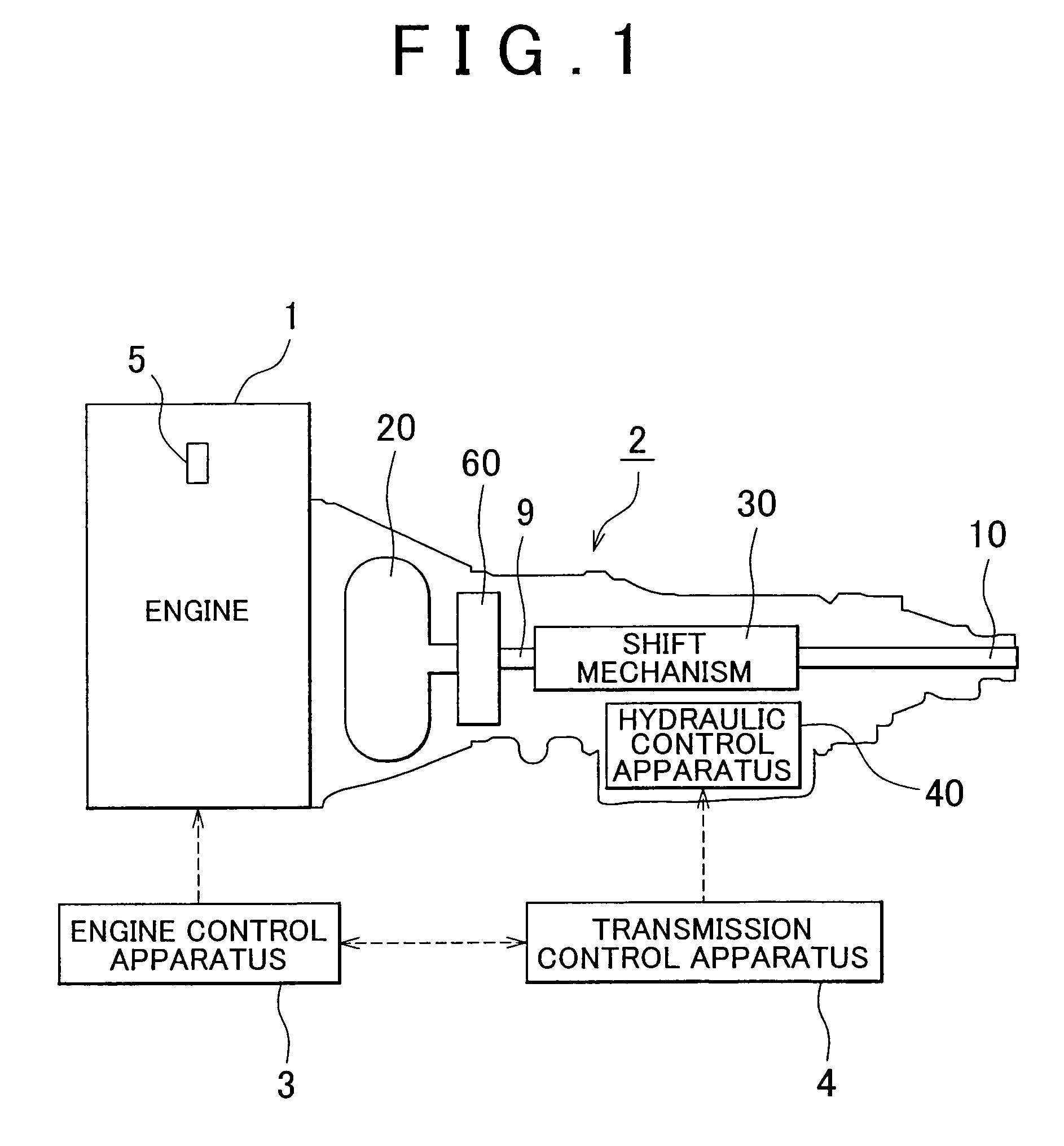
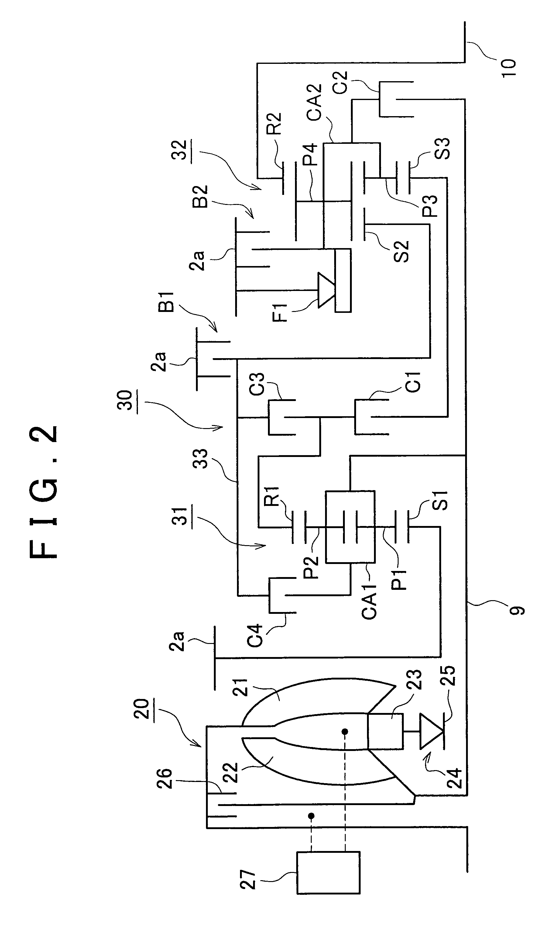
[0060]FIG. 1 is a block diagram schematically showing a powertrain of a vehicle in first, second, and third example embodiments of the invention. FIG. 2 is a skeleton graph showing an example of an automatic transmission 2 shown in FIG. 1, and FIG. 3 is a perspective view showing a frame format of a shift mechanism 30 shown in FIGS. 1 and 2.

[0061]As shown in FIG. 1, the vehicle to which a hydraulic control apparatus for an automatic transmission according to the example embodiments of the invention is provided with an engine 1, the automatic transmission 2, an e...


PUM


Abstract

A hydraulic control apparatus of an automatic transmission estimates the possibility of there being a demand for a shift into a gear lower than the current gear during a power-off downshift operation. If there is a possibility that there will be a demand for a shift into the next gear during the shift, the hydraulic control apparatus starts an operation for supplying an apply preparation hydraulic pressure in preparation for the shift into that next gear.

Description

BACKGROUND OF THE INVENTION[0001]1. Field of the Invention[0002]The invention relates to a hydraulic control apparatus for performing shift control in an automatic transmission provided in a vehicle or the like. More particularly, the invention relates to a hydraulic control apparatus and a hydraulic control method for an automatic transmission, which suppresses shift shock when a shift operation is performed in the transmission.[0003]2. Description of the Related Art[0004]One type of known transmission that transmits torque and rotation speed generated by the engine to the driving wheels appropriately according to the running state of the vehicle is an automatic transmission which automatically establishes the optimum gear ratio between the engine and the driving wheels.[0005]Two examples of such known automatic transmissions that are used in vehicles are planetary gear type transmissions that establish a gear (hereinafter also referred to as “speed”) using a planetary gear set tog...

Claims


Application Information

Patent Timeline
Patent Type & Authority Patents(United States)
IPC IPC(8): F16H61/40F16H31/00F16H59/44F16H59/48F16H61/04F16H61/08F16H61/68F16H61/684F16H61/686
CPCF16H61/061F16H3/663Y10T477/636F16H61/686F16H2061/0444F16H2061/062F16H2200/006F16H2200/2007F16H2200/2023F16H2200/2046F16H2306/14F16H2306/24F16H2061/0496Y10T477/688Y10T477/637F16H3/666
Inventor KONDO, TOMOHIROKONDO, MASAMISATO, TOSHIMITSU
Owner TOYOTA JIDOSHA KK
Why Eureka
Try Eureka