

Control device for automatic transmission
A technology of automatic transmission and control equipment, which is applied in the direction of transmission control, mechanical equipment, vehicle gearbox, etc., to achieve the effect of suppressing shock during engagement and suppressing shift shock
- Summary
- Abstract
- Description
- Claims
- Application Information
AI Technical Summary
Problems solved by technology
Method used
Image

Examples
no. 1 example
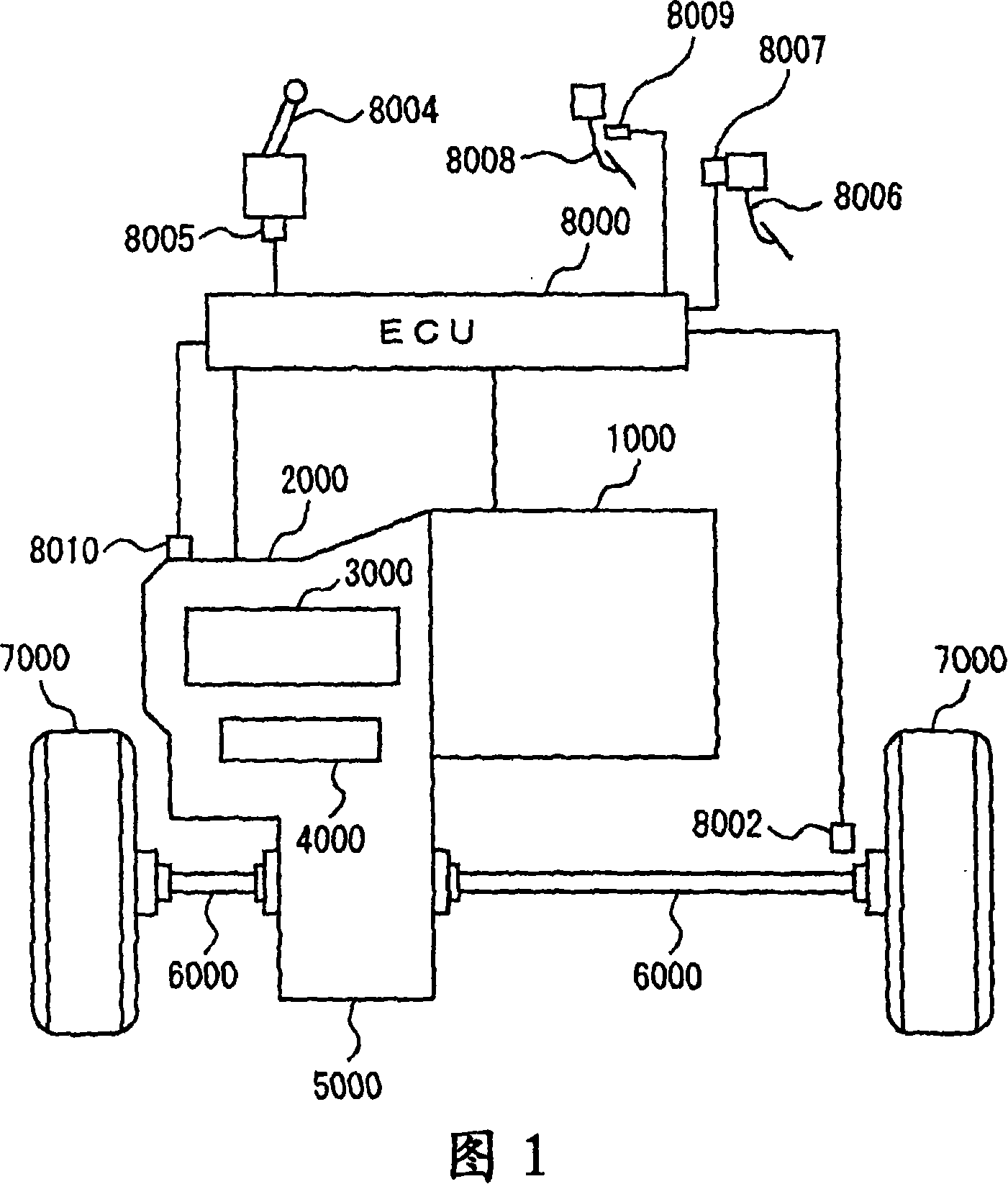
[0025] A vehicle equipped with an automatic transmission control apparatus according to an embodiment of the present invention will be described below with reference to FIG. 1 . The vehicle is an FF (Front Engine Front Drive) vehicle. It should be noted that the vehicle carrying the automatic transmission control apparatus according to the present embodiment may be a type of vehicle other than FF.
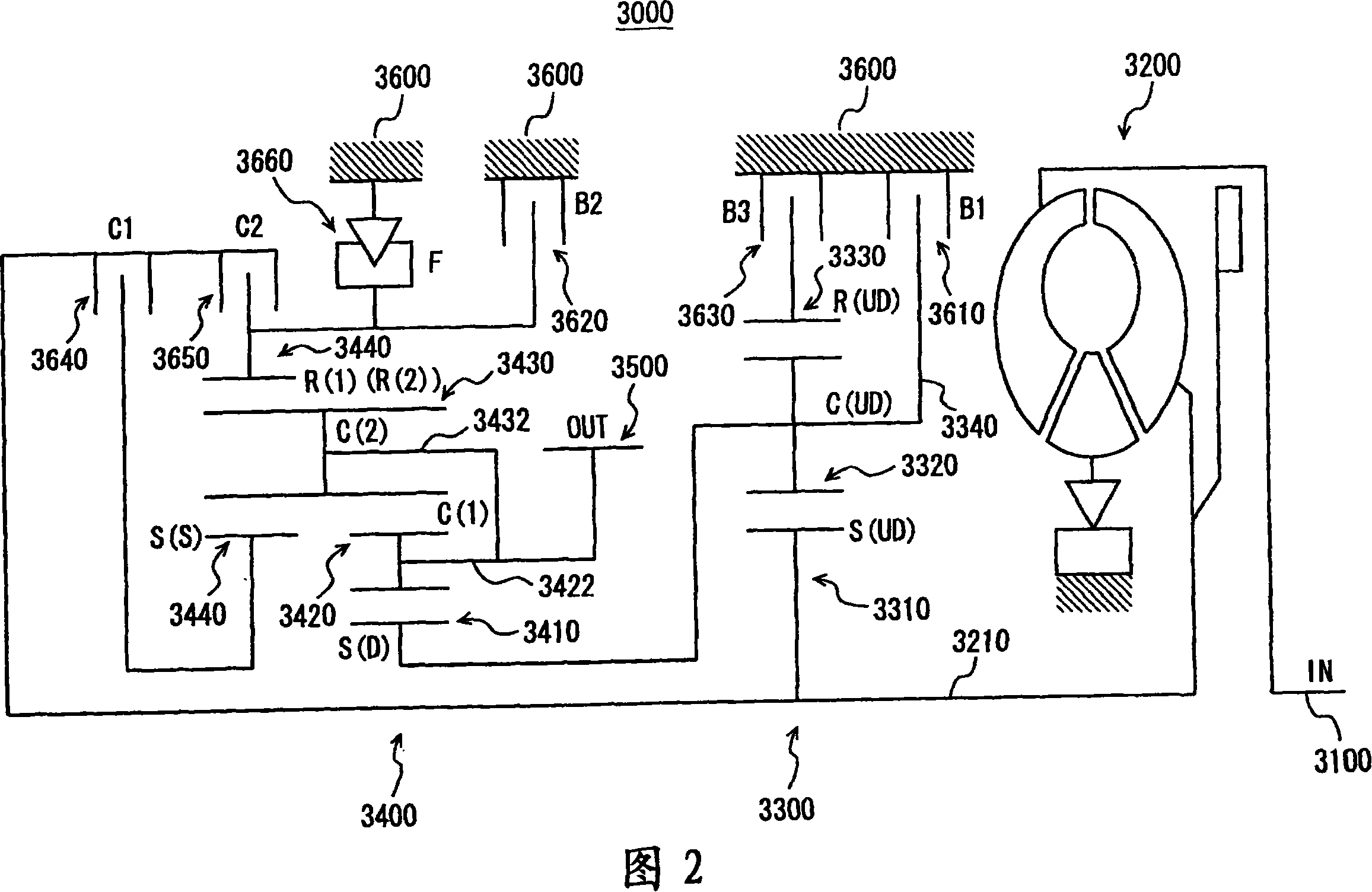
[0026] The vehicle includes an engine 1000, a transmission 2000, a planetary gear unit 3000 constituting a part of the transmission 2000, an oil pressure circuit 4000 constituting a part of the transmission 2000, a differential gear 5000, a drive shaft 6000, front wheels 7000, and an ECU (Electronic Control Unit )8000.
[0027] Engine 1000 is an internal combustion engine that burns a mixture of fuel and air injected from injectors (not shown) in combustion chambers of cylinders. Combustion pushes down the piston in the cylinder to turn the crankshaft. It should be noted that an...
no. 2 example
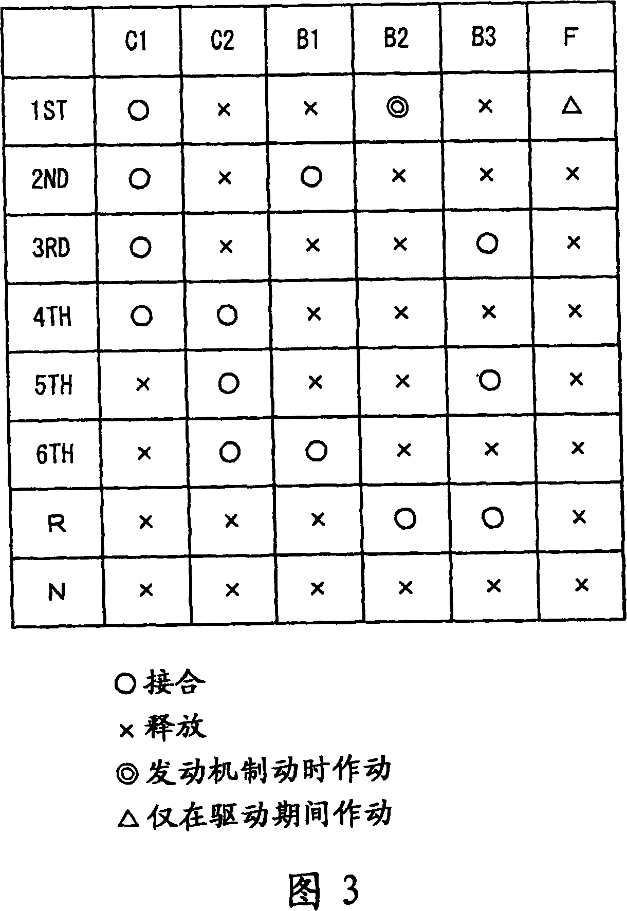
[0060] Next, a second embodiment of the present invention will be described. In this embodiment, based on the slip amount N(SLP) of the torque converter, the clutch-to-clutch (downshift from fourth gear shown in FIG. 3 to third gear) is optimized from the determination of the disengagement side frictional engagement element Waiting time until determination of the frictional engagement element on the engaged side. It should be noted that FIGS. 1 to 3 explained in the first embodiment are also the same in this embodiment. Therefore, a detailed description thereof will not be repeated.
[0061] The map stored in the memory of ECU 8000 serving as the control device according to the present embodiment will be described below with reference to FIG. 6 .
[0062] In FIG. 6 , as in FIG. 4 described above, the horizontal axis represents the slip amount N(SLP) of the torque converter. The vertical axis in FIG. 6 represents the waiting time from disengagement to engagement.
[0063]As...
no. 3 example
[0070] Next, a third embodiment of the present invention will be described. In the present embodiment, the coast down shift line is modified according to the slip amount N(SLP) of the torque converter. More specifically, the output shaft speed of the automatic transmission defining a coast down shift line is varied. Note that FIG. 1 to FIG. 3 described in the first embodiment are the same in this embodiment, as previously described in the second embodiment. Therefore, its detailed description will not be repeated here.
[0071] The map stored in the memory of ECU 8000 serving as the control device according to the present embodiment will be described below with reference to FIG. 8 .
[0072] As shown in FIG. 8 , the map defines the output shaft speed NOUT of the automatic transmission for each range of slip amount N(SLP) of the torque converter, at which output shaft speed NOUT is reached, a coast downshift is determined.
[0073] As shown in FIG. 8 , the smaller the slip a...
PUM
 Abstract
Description
Claims
Application Information