System and method for an enhanced noise shaping for spread spectrum modulation

a spread spectrum modulation and enhanced noise technology, applied in noise generation, automatic control, electrical equipment, etc., can solve the problems of moving the error noise to higher frequencies, increasing the sign change of error around the target signal, etc., to improve emi performance, increase the rate of plurality, and increase the sign change ra

Active Publication Date: 2010-06-22
MONTEREY RES LLC
View PDF51 Cites 13 Cited by
  • Summary
  • Abstract
  • Description
  • Claims
  • Application Information

AI Technical Summary

Benefits of technology

[0015]A frequency synthesizer is described. In particular, the frequency synthesizer includes a modulator circuit for producing a signal of modulated frequency. The frequency synthesizer includes an accumulator for summing a plurality of errors in the modulator circuit. An error sum value is generated. More particularly, the accumulator increases the rate of sign change of the plurality of errors. An error signal modulat...

Problems solved by technology

As a result, the error noise around a target signal shows an increas...

Method used


Image

  • System and method for an enhanced noise shaping for spread spectrum modulation
  • System and method for an enhanced noise shaping for spread spectrum modulation
  • System and method for an enhanced noise shaping for spread spectrum modulation

Examples


Embodiment Construction

[0060]Reference will now be made in detail to the embodiments of the present invention, systems and methods for modulating a phase lock loop (PLL) signal. While the invention will be described in conjunction with the embodiments, it will be understood that they are not intended to limit the invention to these embodiments. Furthermore, in the following detailed description of the present invention, numerous specific details are set forth in order to provide a thorough understanding of the present invention. However, it will be recognized by one of ordinary skill in the art that the present invention may be practiced without these specific details. In other instances, well known methods, procedures, components, and circuits have not been described in detail as not to unnecessarily obscure aspects of the present invention.

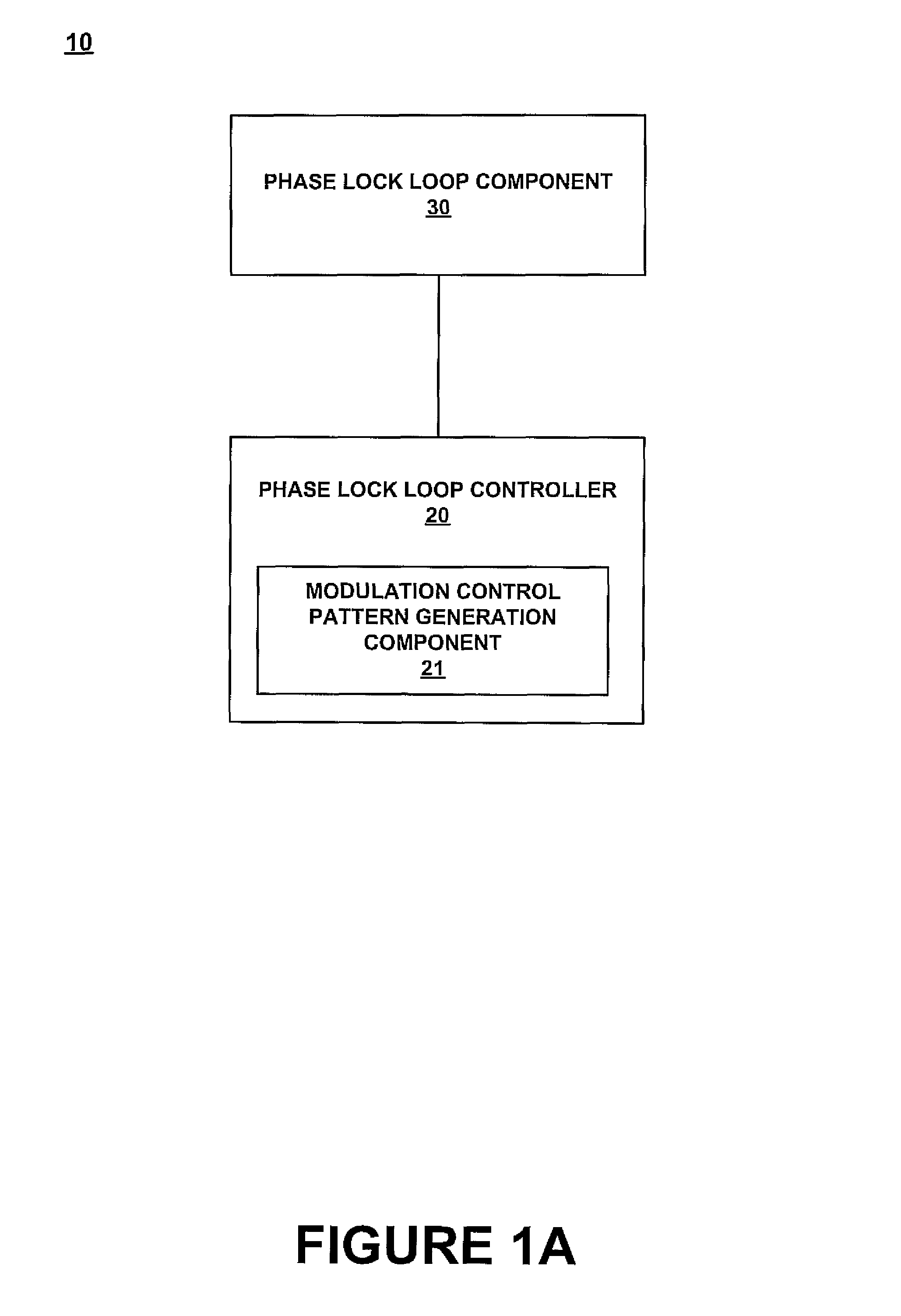
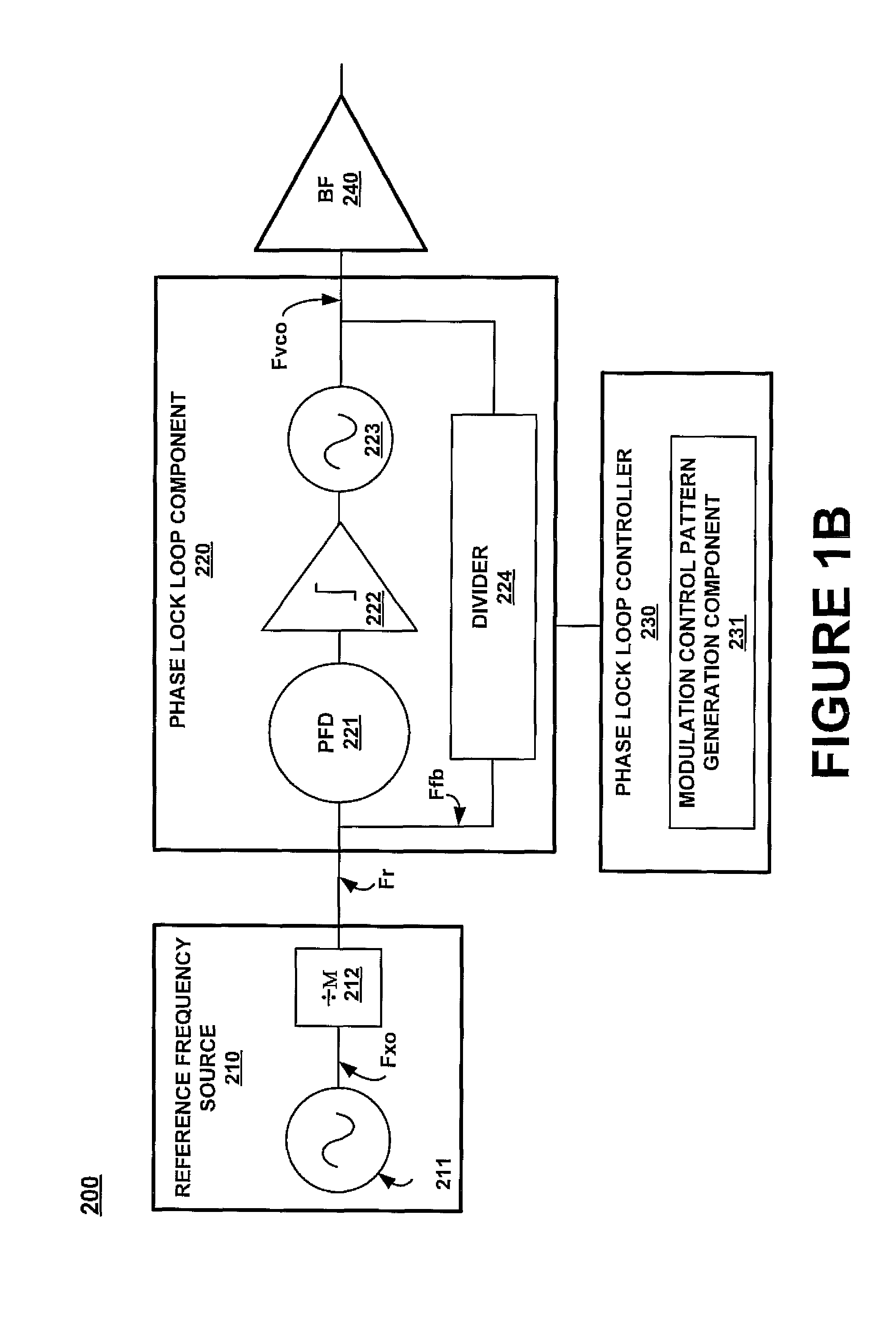
[0061]Present invention phase-locked loop control systems and methods facilitate control of phase-lock loop operations. In one embodiment, phase-lock loop control sys...


PUM


Abstract

A frequency synthesizer is described. In particular, the frequency synthesizer includes a modulator circuit for producing a signal of modulated frequency. The frequency synthesizer includes an accumulator for summing a plurality of errors in the modulator circuit. An error sum value is generated. More particularly, the accumulator increases the rate of sign change of the plurality of errors. An error signal modulator is coupled to the accumulator and modulates an index that is associated with a current error based on the error sum value. The index that is modulated is used for selecting a feedback loop divider count value used for dividing a frequency of the signal. As a result, the error noise around a target signal shows an increased sign change of error, which moves the error noise to higher frequencies. This improves EMI performance.

Description

CROSS REFERENCE TO RELATED APPLICATIONS[0001]This application is a continuation in part and claims the benefit of and is related to U.S. patent application Ser. No. 11 / 172,691 by Shuliang Li filed on Jun. 30, 2005 now U.S. Pat. No. 7,405,629 “FR EQUENCY MODULATOR CIRCUIT AND METHOD THAT USES MULTIPLE VECTOR ACCUMULATION TO ACHIEVE FR ACTIONAL-N FR EQUENCY SYNTHESIS”, all of which are assigned to the assignee of the present invention, which are incorporated herein by reference.[0002]This application is related to the following co-pending Applications:[0003]U.S. patent application Ser. No. 11 / 590,385 entitled “A PHASE LOCK LOOP CONTROL SYSTEM AND METHOD” by Shuilang Li filed on Oct. 30, 2006;[0004]U.S. patent application Ser. No. 11 / 590,361 entitled “A PHASE LOCK LOOP CONTROL ERROR SELECTION SYSTEM AND METHOD” by Shuilang Li filed on Oct. 30, 2006;[0005]U.S. patent application Ser. No. 11 / 590,362 entitled “A PHASE LOCK LOOP CONTROL SYSTEM AND METHOD WITH NON-CONSECUTIVE FEEDBACK DIVID...

Claims


Application Information

Patent Timeline
IPC IPC(8): H03B29/00H03L7/18
CPCH03C3/0933H03C3/0925
Inventor LI, SHULIANG
Owner MONTEREY RES LLC
Why Eureka
Try Eureka