Timepiece and portable device

a portable device and timepiece technology, applied in the field of timepieces and portable devices, can solve the problems of affecting the sound quality of the gong, so as to achieve the effect of pleasing the sound

Inactive Publication Date: 2010-06-22
SEIKO EPSON CORP
View PDF8 Cites 16 Cited by
  • Summary
  • Abstract
  • Description
  • Claims
  • Application Information

AI Technical Summary

Benefits of technology

[0007]A timepiece and a portable device having a sound source that produces sound when the sound source is struck and vibrates according to the present invention enable easily setting the spring force of each spring so that a pleasing sound is produced.

Problems solved by technology

However, in a mechanism such as this that has springs urging the hammer in two different directions disposed to the hammer, the hammer may not separate from the gong after striking the gong, and may therefore inhibit vibration of the gong, if the spring force of the spring that urges the hammer to the gong is high.
On the other hand, if the force of the spring that pulls the hammer away from the gong is strong, the hammer strikes the gong with less force and the gong may not produce a good sound.
However, if the springs urging in opposite directions are attached directly to the hammer, adjusting the force of each spring appropriately is difficult.
More specifically, in a timepiece having an internal sound source that produces sound when struck by a hammer, a gap is generally provided where the case and the back cover are joined so that the sound produced when the hammer strikes the sound source can be heard outside the case, and the timepiece is therefore not sufficiently water resistant.
Furthermore, if packing is provided between the case and the back cover in order to make the timepiece water resistant, or packing is used to make the inside of the case airtight, the air inside the case does not vibrate easily and the resulting sound is therefore small.
More specifically, if plural sound sources are struck using a single striking force transmission member, the striking force will be dispersed and outputting a good sound may not be possible.

Method used


Image

  • Timepiece and portable device
  • Timepiece and portable device
  • Timepiece and portable device

Examples


embodiment 1

[0105]A first embodiment of the invention is described below with reference to FIG. 1 to FIG. 5.

[0106]1. General Configuration

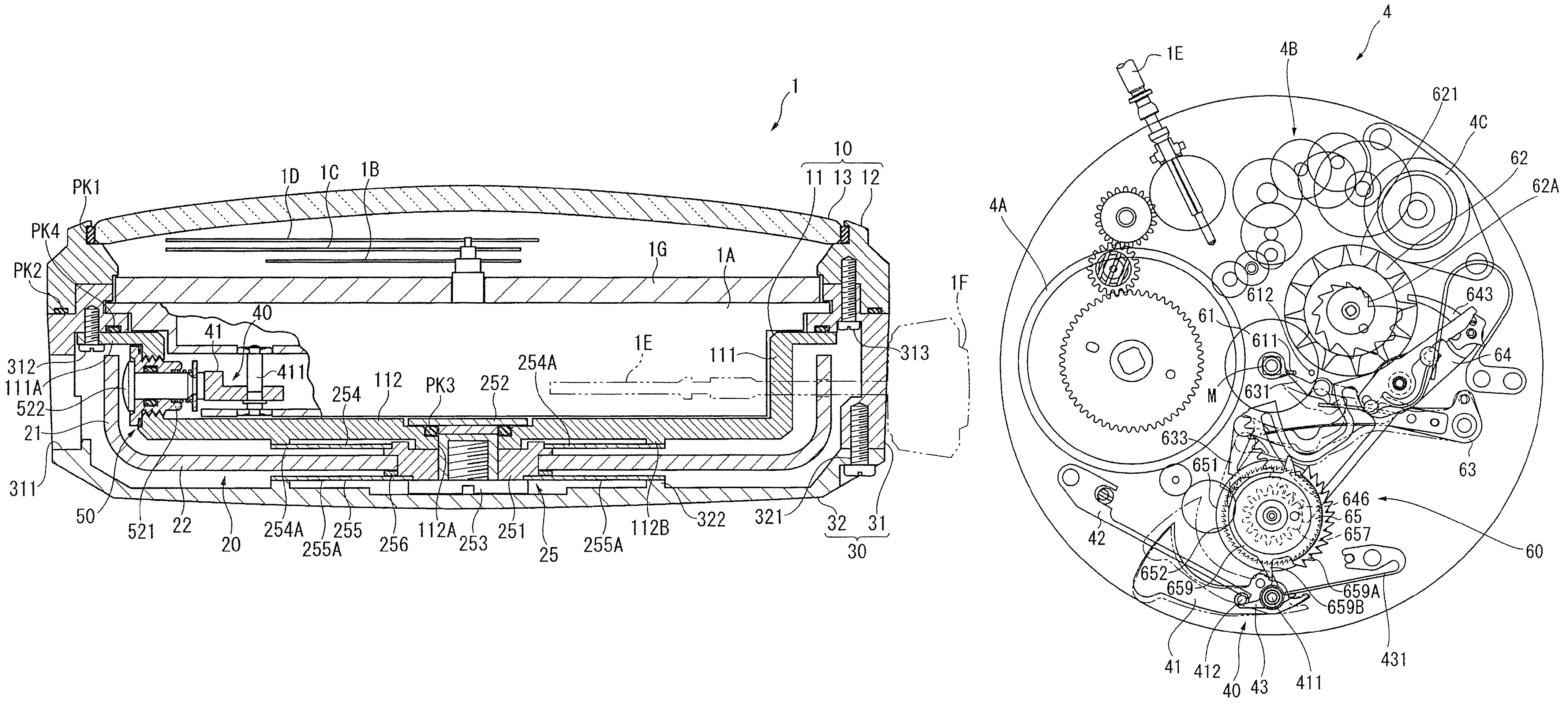
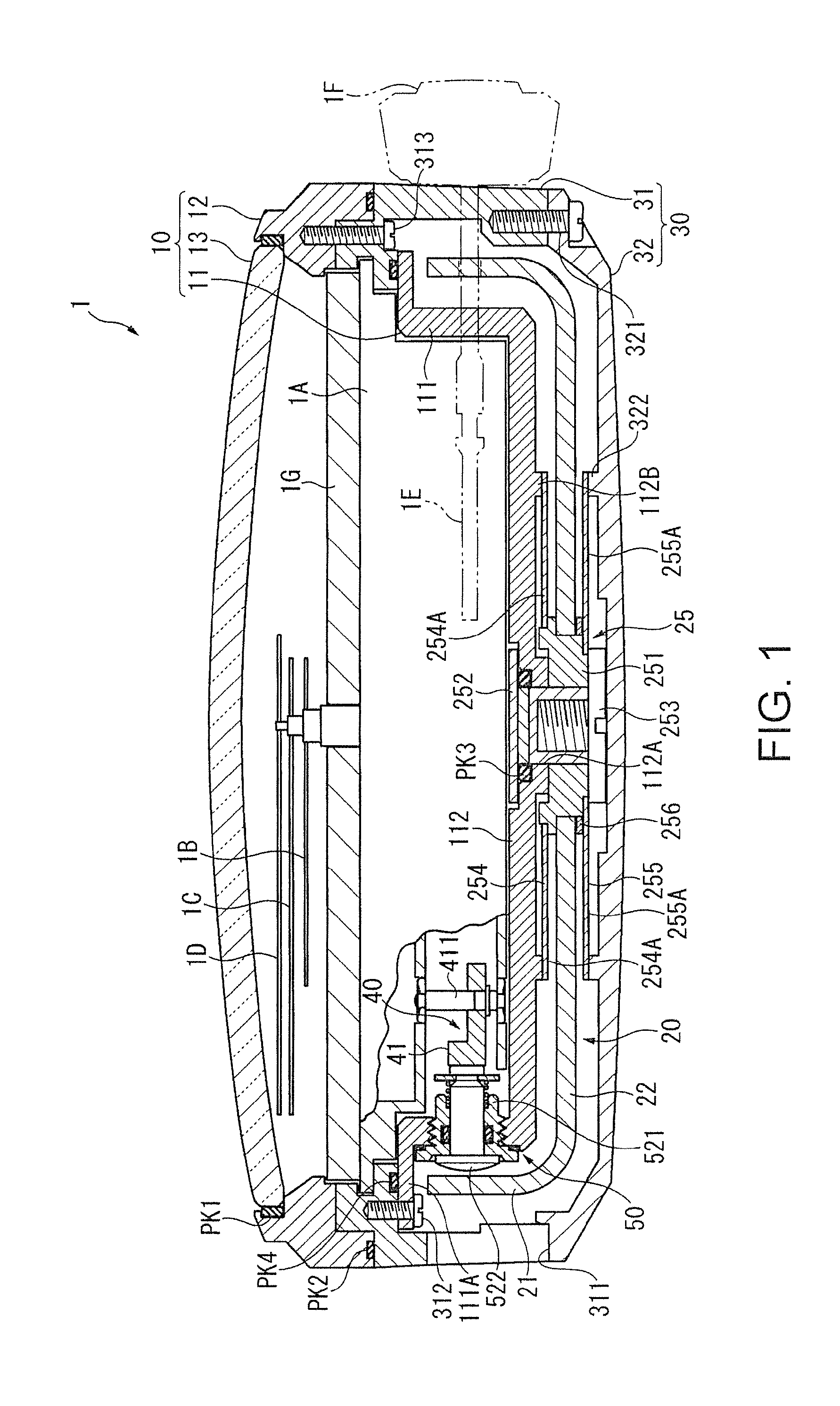
[0107]FIG. 1 is a vertical section view of a timepiece 1 according to a first embodiment of the invention. The timepiece 1 has a movement 1A as the main timekeeping mechanism, an inside case 10 that houses the movement 1A, a bell 20 that is a bowl-shaped sound source disposed outside the inside case 10, and an outside case 30 that encloses the bell 20. The timepiece 1 according to this embodiment of the invention is an electronically controlled mechanical timepiece that drives the hands using the drive power from a spring, and supplies power produced by the drive power of a spring to an electronic circuit to govern the speed.

[0108]While not shown in detail in the figures, the movement 1A has a main spring, a drive wheel train that drives the hour hand 1B, minute hand 1C, and second hand 1D using drive power from the main spring, a generator that converts driv...

embodiment 2

[0205]A second embodiment of the invention is described next with reference to FIG. 6 to FIG. 8.

[0206]This embodiment of the invention uses a gong instead of a bell as the sound source, and the timepiece according to this embodiment of the invention has a repeater mechanism.

[0207]The timepiece according to this embodiment of the invention has a see-through back with a protective crystal disposed in the back cover.

[0208]The striking force transmission member in this embodiment is also different from the first embodiment.

[0209]Other than these main differences, the timepiece according to this embodiment of the invention is substantially the same as the timepiece 1 described in the first embodiment above.

[0210]FIG. 6 is a vertical section view of the timepiece 7 according to this embodiment of the invention, and FIG. 7 is a horizontal section view of the timepiece 7. Parts of the movement other than the hammer arm 41 and the hammer trip 43 are not shown in FIG. 7.

[0211]The timepiece 7 ...

embodiment 3

Third Variation of Embodiment 3

[0294]FIG. 14 shows the hammer pin unit 90″ in another variation of the third embodiment.

[0295]In this embodiment the outside sleeve 901″ is screwed in from the inside of the inside case member 811′, and the fastening ring 907″ is screwed onto the end of the outside sleeve 901″ protruding from the outside of the inside case member 811′ with a washer 908 therebetween. A key formed on the outside circumference of the washer 908 fits into a notch formed in the inside circumference part of the outside sleeve 901″, thereby preventing the washer 908 from turning. The elastic sheet 906 is thus not abraded when the fastening ring 907″ is screwed on, and the elastic sheet 906 can be compressed uniformly.


PUM


Abstract

A timepiece having a movement having a hammer and a hammer drive device that drives the hammer, a case that houses the movement, a sound source that produces sound by vibrating when struck by the hammer, and a striking force transmission member that can move bidirectionally between the hammer and the sound source, and transmits the striking force of the hammer to the sound source.

Description

BACKGROUND[0001]1. Field of Invention[0002]The present invention relates to a timepiece and a portable device that have a sound source such as a gong or a bell.[0003]2. Description of Related Art[0004]Sonnerie timepieces that have a C-shaped gong and a hammer for striking the gong are known from the literature. See, for example, “2002 Guide to the latest wristwatches with full specifications,” K. K. Gakushu Kenkyusha, published Mar. 1, 2002, page 117. The timepiece in this example has the gong fastened to the base plate and disposed along the outside of the movement. The hammer is attached to the base plate on the inside of the gong so that the hammer can pivot, and is driven at a predetermined time by the drive power of a spring. A spring that returns the hammer that strikes the gong to its original position is also attached to the base plate.[0005]The sonnerie timepiece according to the related art described above strikes the gong directly with a hammer, and a spring that urges th...

Claims


Application Information

Patent Timeline
Patent Type & Authority Patents(United States)
IPC IPC(8): G04B21/00
CPCG04B21/06G04B23/10G04B23/026G04B21/12
Inventor MOTEKI, MASATOSHIOZAWA, NORIAKI
Owner SEIKO EPSON CORP
Why Eureka
Try Eureka