
Method of fabricating muntin bars for simulated divided lite windows

a technology of lite windows and muntin bars, which is applied in the direction of flooring, building repairs, units with parallel planes, etc., can solve the problems of high cost, relatively high assembly process, and relatively high cost of fabrication

Inactive Publication Date: 2010-06-29
QUANEX IG SYST INC
View PDF45 Cites 10 Cited by
  • Summary
  • Abstract
  • Description
  • Claims
  • Application Information

AI Technical Summary

Benefits of technology

The solution efficiently simulates the traditional divided lite window appearance with reduced material and labor costs, preventing delamination and maintaining aesthetic appeal by using foam strips that are securely attached without adhesives, even on curved surfaces.

Problems solved by technology

While these windows are attractive and have functioned for many years, they are relatively expensive to fabricate.
The expense is particularly high when a consumer desires an insulating window having spaced panes of glass sealed together by a perimeter spacer.
In addition to the cost of materials, the assembly process is also relatively expensive.
Thus, although consumers desire the aesthetic properties of traditional divided lite windows, most are unwilling to pay for a true divided lite window.
Although these solutions provide options for consumers, each has visual drawbacks when compared with traditional muntin bars.
Although this product achieved acceptance by the consumer because of its visual appearance, the insulating window manufacturers objected to the relatively large amount of labor required to size, cut, and install the material strips.
Another problem encountered with this product occurs when the material strips are stretched during installation or applied to the outside of a curved muntin.
It has been found that the strips relax overtime and delaminate causing the window to have an unattractive appearance.

Method used


Image

  • Method of fabricating muntin bars for simulated divided lite windows
  • Method of fabricating muntin bars for simulated divided lite windows
  • Method of fabricating muntin bars for simulated divided lite windows

Examples


Embodiment Construction

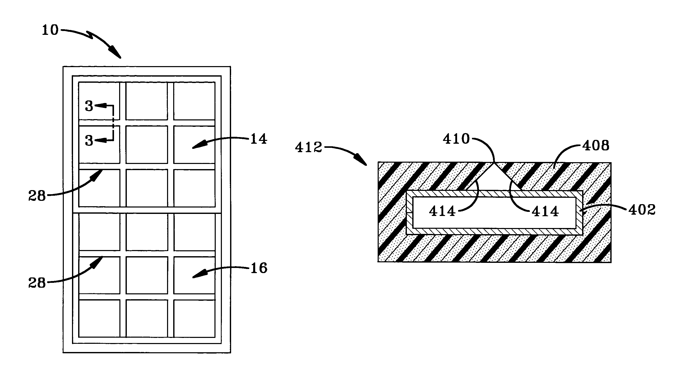
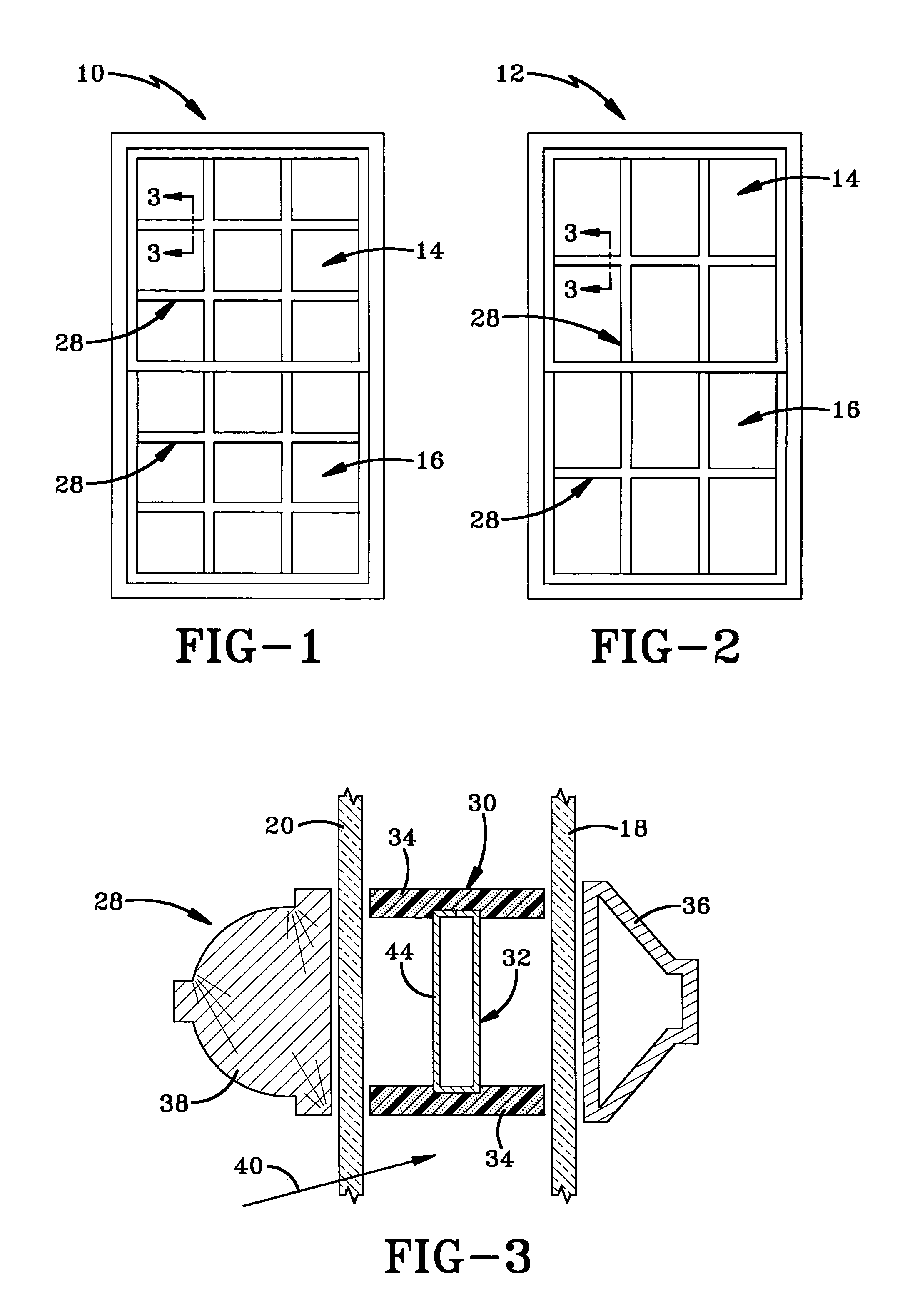
[0071]Windows having muntin bar grids fabricated according to the concepts of the present invention are indicated generally by the numerals 10 and 12 in FIGS. 1 and 2, respectively. Window 10 is an insulating window having an upper sash 14 and a lower sash 16. Each sash 14 and 16 includes a pair of glass sheets 18 and 20 that are spaced apart by a perimeter spacer 22 having a desiccant matrix 24 (see FIG. 10). Other perimeter spacers 22A and 228 (FIGS. 11A and 11B) may also be used without departing from the concepts of the present invention. As discussed above in the Background of the Invention section of this Application, this type of insulating window is desired by consumers because of its energy saving properties. As also discussed above, consumers desire the appearance of traditional windows fabricated from multiple glass panes mounted in a wooden muntin bar grid. If window 10 were manufactured in the traditional method, eighteen panes of glass would be required in addition to ...


PUM

PropertyMeasurementUnit
insulatingaaaaaaaaaa
flexibleaaaaaaaaaa
widthaaaaaaaaaa

Abstract

A method for fabricating muntin grid pieces includes steps that attach an outer muntin grid element to an inner muntin grid element to form a two piece muntin grid piece. The outer muntin grid element surrounds at least three sides of the inner muntin grid element and may be held to the outer muntin grid element without connectors such as adhesive. The outer muntin grid element may be a slit tube that is spread open to be positioned over the inner muntin grid element.

Description

CROSS REFERENCE TO RELATED APPLICATIONS[0001]This application is a continuation-in-part application claiming priority from U.S. application Ser. No. 09 / 637,722, filed Aug. 11, 2000 now U.S. Pat. No. 6,425,221 which claimed priority from U.S. Provisional Application Ser. No. 60 / 148,842, filed Aug. 13, 1999; the disclosures of both applications are incorporated herein by reference.BACKGROUND OF THE INVENTION[0002]1. Technical Field[0003]This invention generally relates to windows having muntin bars that simulate the appearance of traditional divided lite windows having individual panes of glass set in wooden muntin bars. More particularly, the present invention relates to a method of fabricating muntin bars on automated machinery for use in simulated divided lite windows. Specifically, the present invention relates to a method of automatically sizing, cutting, and joining foam strips to the top and bottom edges of traditional thin metal inner muntin grid elements for use in insulating...

Claims


Application Information

Patent Timeline
Patent Type & Authority Patents(United States)
IPC IPC(8): E06B9/01E06B3/66E06B3/667
CPCE06B3/6604E06B3/667E06B3/6675Y10T29/53013Y10T29/49794Y10T29/4978Y10T29/53383Y10T29/49616Y10T29/49792Y10T29/49798Y10T29/49771Y10T29/49906Y10T29/5142
Inventor REICHERT, GERHARD
Owner QUANEX IG SYST INC
Learn More