Anti-slip crutch tip apparatus and method

a technology of anti-slip crutch and tip, which is applied in the field of anti-slip crutch tip apparatus and method, can solve the problems of user's loss of balance, none of the known tips have adequately alleviated the slipping problem, etc., and achieve the effect of preventing hydroplaning and sideways slippage of the crutch tip, and relieving pressure built-up

Active Publication Date: 2010-07-06
LASOTA GARY S
View PDF26 Cites 11 Cited by
  • Summary
  • Abstract
  • Description
  • Claims
  • Application Information

AI Technical Summary

Benefits of technology

[0006]A second aspect of the present invention provides a crutch support tip apparatus for preventing sideways slipping of a crutch support, the crutch support tip apparatus comprising: a tip body, having a crutch leg receiving end, an opposing base support end, and a sidewall that extends between the crutch receiving end and the base support end, the crutch leg receiving end having a top axial opening configured to receive the leg of a crutch support, and the base support end having a bottom diameter that is larger than the diameter of the crutch leg receiving end; a circumferential contact surface, located at the extent of the outermost diameter of the bottom of the base support end, the circumferential contact surface being concaved so that the outer-most edge of the concaved circumferential contact surface forms the perimeter of a suction-cup-like recess of the bottom of the base support end of the tip body; and a relief tunnel situated to extend through the structure of the tip body between the sidewall of the tip body, above the circumferential contact surface, and a portion of a groove formed on the bottom of the base support end, wherein the groove is located radially within the diameter of the circumferential contact surface of the base support end.
[0007]A third aspect of the present invention provides a method of preventing slipping of a crutch support device tip, the method comprising: providing an anti-slip crutch tip apparatus including: a tip body, having a first end and an opposing second end, wherein the first end of the tip body includes a crutch leg opening extending axially within a generally frustoconical section of the tip body, the crutch leg opening configured to receive a portion of a crutch leg, and wherein the second end of the tip body includes a surface contact portion located at the extent of a generally cylindrical section of the tip body, the surface contact portion having a circumferential contact surface being concaved so that the outer-most edge of the concaved circumferential contact surface forms the perimeter of a suction-cup-like recess of the extent of the generally cylindrical section of the second end of the tip body; and a relief tunnel situated to extend through the structure of the tip body between the sidewall of the generally cylindrical section of the tip body, above the circumferential contact surface, and a portion of a groove formed on the surface contact portion, wherein the groove is located radially within the diameter of the circumferential contact surface of the second end of the tip body; compressing the circumferential contact surface of the tip body against a crutch support surface; and relieving pressure built-up under the suction-cup-like recess of the extent of the generally cylindrical section of the second end of the tip body by allowing the built-up pressure to escape through the relief tunnel extending between the groove formed on the surface contact portion and the sidewall of the generally cylindrical section of the tip body, thereby preventing hydroplaning and sideways slippage of the crutch tip.

Problems solved by technology

Reliable support is especially important when the support device is employed on wet, icy, or otherwise slick surfaces because such surface conditions may cause the tip of the support device (hereinafter referred to interchangeably as a crutch tip) to slip sideways causing the user of the device to lose balance and fall possibly leading to injury.
However, none of the known tips have adequately alleviated the slipping problem.

Method used


Image

  • Anti-slip crutch tip apparatus and method
  • Anti-slip crutch tip apparatus and method
  • Anti-slip crutch tip apparatus and method

Examples


Embodiment Construction

[0014]Although certain embodiments of the present invention will be shown and described in detail, it should be understood that various changes and modifications may be made without departing from the scope of the appended claims. The scope of the present invention will in no way be limited to the number of constituting components, the materials thereof, the shapes thereof, the relative arrangement thereof, etc., and are disclosed simply as an example of an embodiment. The features and advantages of the present invention are illustrated in detail in the accompanying drawings, wherein like reference numerals refer to like elements throughout the drawings.

[0015]As a preface to the detailed description, it should be noted that, as used in this specification and the appended claims, the singular forms “a”, “an” and “the” include plural referents, unless the context clearly dictates otherwise.

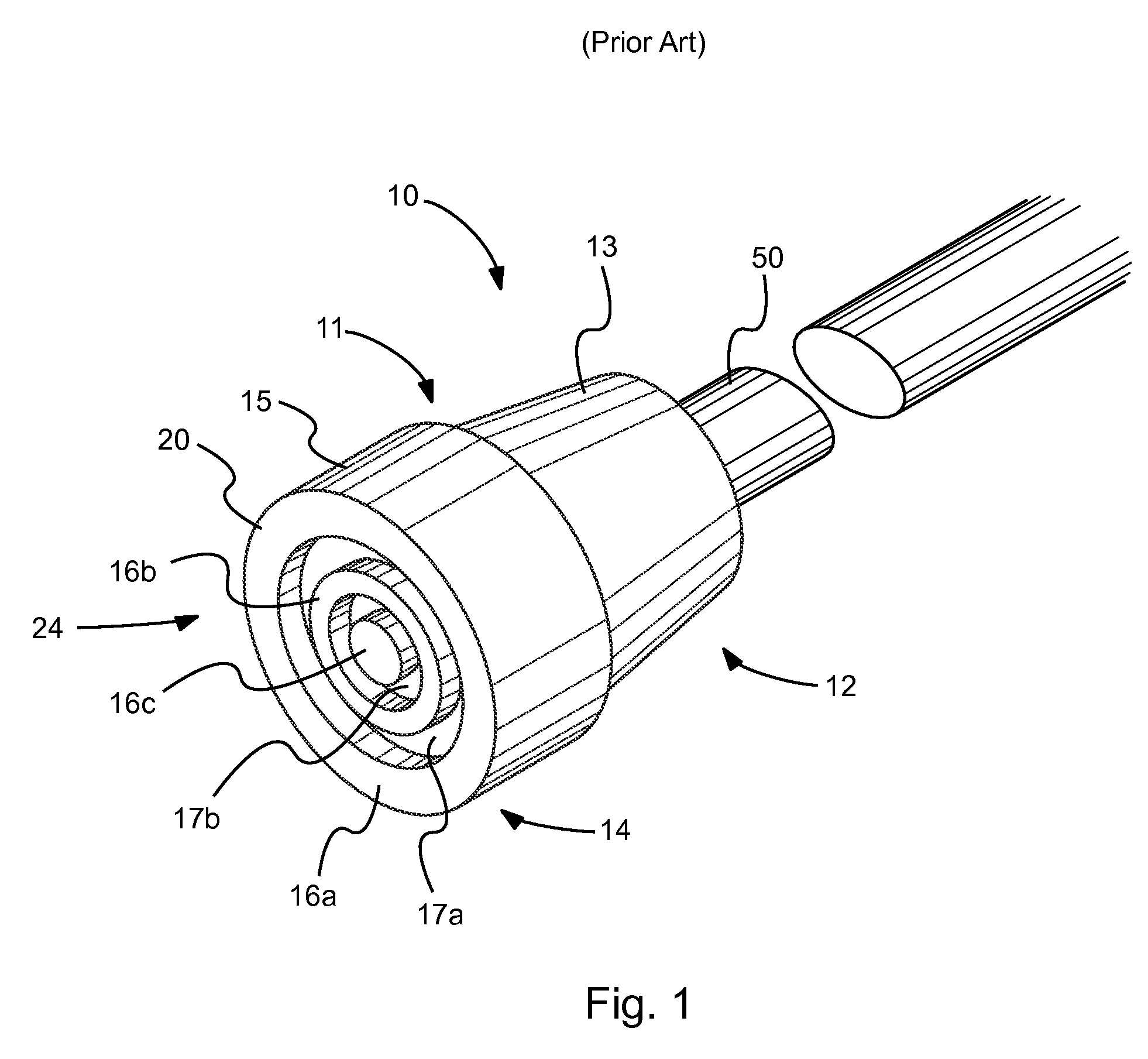
[0016]Referring to the drawings, FIG. 1 depicts a perspective view of standard crutch support ti...


PUM


Abstract

Provided is an anti-slip crutch tip apparatus that includes at least one vent opening, located on the side wall of a generally cylindrical section of a crutch tip body and extending into the tip body, so that the vent opening is surrounded by structure forming a portion of the generally cylindrical section of the tip body The at least one vent opening is in physical communication with a portion of at least one channel formed into a surface contact portion of the tip body, so that an unbroken fissure in the tip body resides as a structural breach extending between the side-wall entrance of the at least one opening and the physically communicative association of the at least one vent opening with the portion of the at least one channel. A corresponding method of preventing slipping of a support device tip is also provided.

Description

BACKGROUND OF THE INVENTION[0001]1. Technical Field[0002]This invention relates generally to an apparatus and method for preventing slipping of crutch tips, cane tips, walker feet tips, and / or tips of other similar support devices. More particularly, this invention provides a support device comprising a side-wall vented tip configuration for relieving pressure buildup to prevent the support device tip from hydroplaning sideways on a wet, icy, or otherwise slick surface. A corresponding method of preventing slipping of a support device tip is also provided.[0003]2. Related Art[0004]Crutches, canes, walkers, and other similar support devices have been used for many years by numerous individuals in need of motive assistance and physical support. When an individual utilizes such a device for motive assistance, it is critical that the physical support provided by the device is steadfast during operation of the device, so that the individual can safely rely on the assistance of the device...

Claims


Application Information

Patent Timeline
Patent Type & Authority Patents(United States)
IPC IPC(8): A45B9/04
CPCA61H3/0288
Inventor LASOTA, JAMES E.
Owner LASOTA GARY S
Why Eureka
Try Eureka