Vertical take-off unmanned aerial vehicle auxiliary take-off system

A vertical take-off, unmanned aerial vehicle technology, applied in control/adjustment systems, non-electric variable control, instruments, etc., can solve the problems of aircraft take-off and landing damage, violent ups and downs of aircraft height, rollover, etc., to achieve fast and safe take-off, easy effect of operation

Active Publication Date: 2017-05-10
广西圣尧智能科技有限公司
View PDF5 Cites 8 Cited by
  • Summary
  • Abstract
  • Description
  • Claims
  • Application Information

AI Technical Summary

Problems solved by technology

[0005] The manual mode mainly depends on the personal operation of the pilot. The input signal of the remote control directly determines the size of the throttle of the aircraft. During the take-off process, manual operation needs to give the aircraft a large throttle in a short time, which is easy to cause misoperation. The amount of throttle is based on the pilot's own experience level. If the throttle is too small, it will not be able to take off. In the case of uneven ground, the aircraft is prone to rollover or skidding and other dangerous situations. If the throttle is too large, then takeoff Afterwards, additional operations are required to return the throttle and altitude of the aircraft to normal levels, which may easily cause severe fluctuations in the altitude of the aircraft and even directly touch the ground, causing damage to the landing and landing parts of the aircraft.
[0006] The more popular in the market is the automatic mode, which pre-determines a desired altitude for the aircraft, and then gradually increases the throttle until the aircraft leaves the ground. Dangerous situations such as side slipping or rollover

Method used


Image

  • Vertical take-off unmanned aerial vehicle auxiliary take-off system
  • Vertical take-off unmanned aerial vehicle auxiliary take-off system
  • Vertical take-off unmanned aerial vehicle auxiliary take-off system

Examples


Embodiment Construction

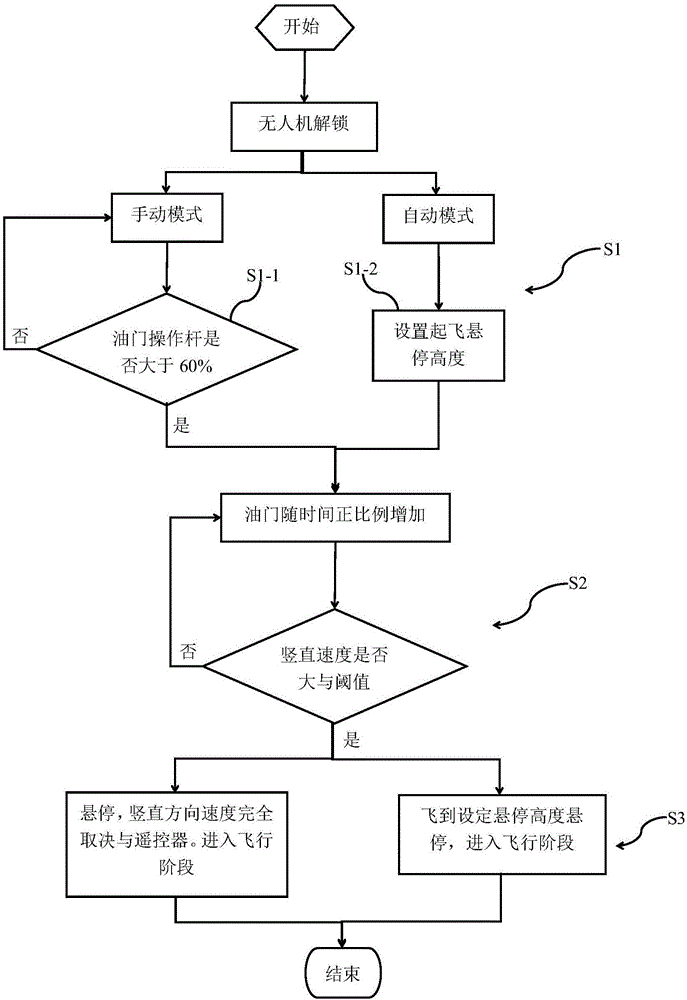
[0025] In order to make the technical means, creative features, goals and effects achieved by the present invention easy to understand, the following embodiments are combined with the accompanying drawings to describe the vertical take-off UAV assisted take-off system of the present invention in detail.

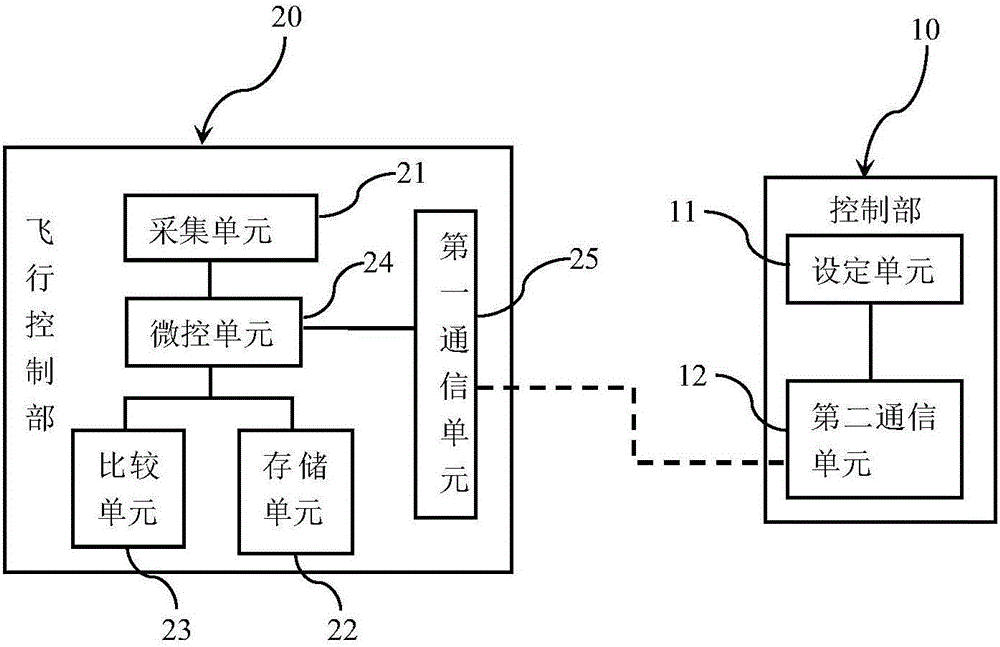
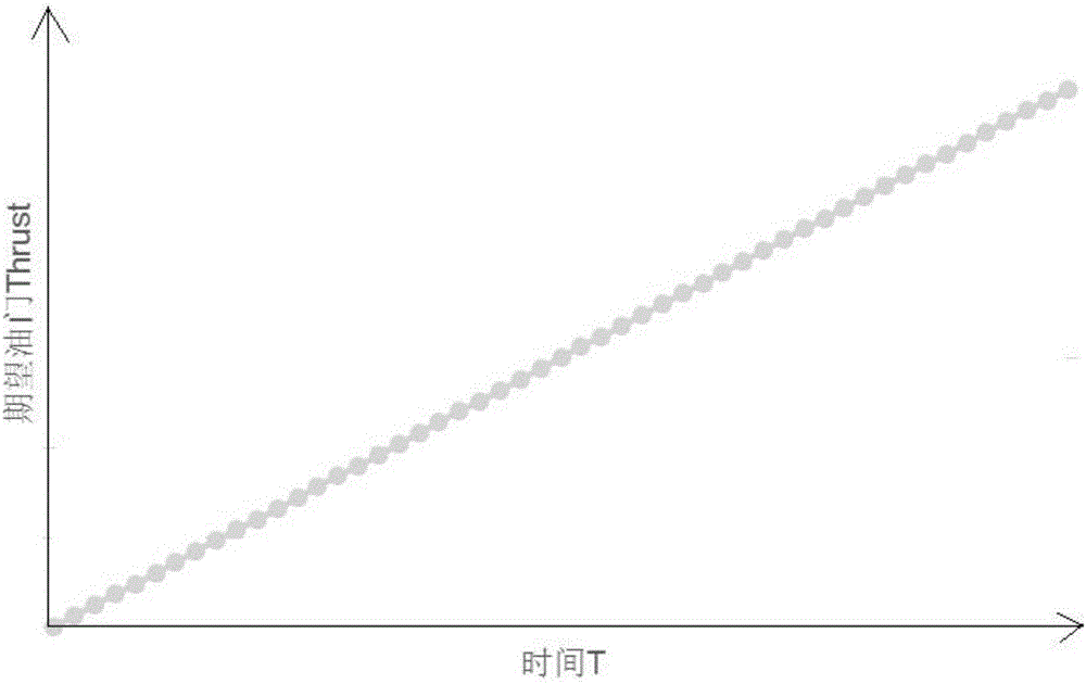
[0026] Such as figure 1 As shown, the auxiliary take-off system 100 for vertical take-off UAV includes: a control unit 10 and a flight control unit 20 .

[0027] The control unit 10 is used to control the flight of the drone, and the control unit 10 is a remote controller or a ground station. The control unit 10 includes: a setting unit 11 and a first communication unit 12 .

[0028] The setting unit 11 is used for setting the control signal. The control signal includes: the way to start each rotor of the drone, the size of the throttle, etc., which are used to control the flying speed, hover, dive, etc. of the drone. The first communication unit 12 is used for communicati...


PUM


Abstract

The invention provides a vertical take-off unmanned aerial vehicle auxiliary take-off system. A vertical speed threshold, an accelerator and time proportionality coefficient and the hovering height after successful take-off of an unmanned aerial vehicle are stored in a storage unit, an acquisition unit can acquire the vertical speed of the unmanned aerial vehicle, a comparison unit can compare the vertical speed with the threshold, and a micro-control unit controls rotary wings producing lifting force to be started according to a take-off signal, controls the accelerator to proportionally increase along with time according to the proportionality coefficient and controls stop of increasing of the accelerator according to the comparison result of the comparison unit so that the unmanned aerial vehicle is enabled to rapidly acquire the vertical speed to leave the ground in a short period of time. Therefore, the unmanned aerial vehicle is enabled to rapidly and safely take off in the severe environment, and side slipping and side turning can be avoided when the unmanned aerial vehicle leaves the ground by application of the vertical take-off unmanned aerial vehicle auxiliary take-off system so that operation of the unmanned aerial vehicle is enabled easier.

Description

technical field [0001] The invention belongs to the technical field of unmanned aerial vehicles, and in particular relates to an auxiliary take-off system for a vertical take-off unmanned aerial vehicle. Background technique [0002] In recent years, the market of UAVs has been booming, and the application fields have become more and more extensive. Whether it is agricultural plant protection, power inspection, forest fire prevention or maritime search and rescue, UAV products have been widely used in many traditional industries. [0003] However, in the daily use of UAV products, they often encounter harsh take-off environments, such as uneven ground or high wind speed on the ground, which makes it difficult or failed to take off, which greatly limits the application scenarios and capabilities of UAV products. market space. [0004] Most of the UAV products in the current market provide two mainstream operation modes: remote control manual and ground station automatic. ...

Claims


Application Information

Patent Timeline
Patent Type & Authority Applications(China)
IPC IPC(8): G05D1/10
CPCG05D1/101
Inventor 张杰陈昱
Owner 广西圣尧智能科技有限公司
Why Eureka
Try Eureka