Locking handle

a technology of locking handle and handle, which is applied in the direction of coupling device connection, coupling parts engagement/disengagement, support structure mounting, etc., and can solve the problems of high cost and inconvenient operation

Inactive Publication Date: 2010-07-06
NEXTRONICS ENG CORP
View PDF8 Cites 18 Cited by
  • Summary
  • Abstract
  • Description
  • Claims
  • Application Information

AI Technical Summary

Benefits of technology

[0012]The present invention has advantageous effects as follows. The grip is integrally formed at an end of the shell. Thus, the grip and the shell can use the same molding. Thus, the molding costs are reduced. The fixing part is disposed in the hole of the shell and stretches to the accommodating space of the shell. The elastic part is compressed between the fixing part and the stopping portion. Users can pull the grip to move the shell relative to the locking part and compress the elastic part, and thus lock the hook. The operation is easier compared to the prior art.
[0013]In order to further understand the characteristics and technical contents of the present invention, a detailed description is made with reference to the accompanying drawings. However, it should be understood that the drawings are illustrative only but not used to limit the present invention thereto.

Problems solved by technology

Hence, the cost is high.
The operation is inconvenient.

Method used


Image

  • Locking handle
  • Locking handle
  • Locking handle

Examples


Embodiment Construction

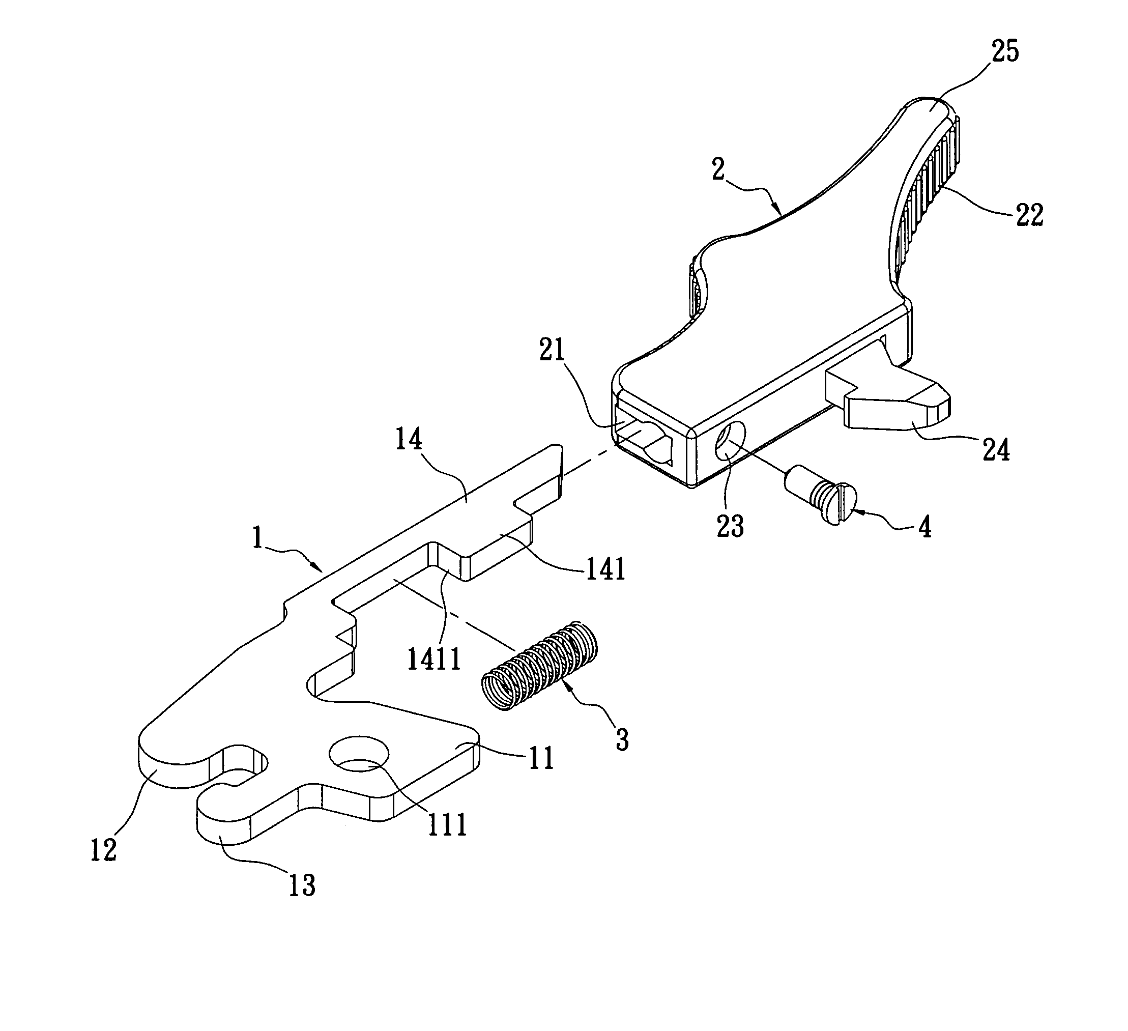
[0021]Please refer to FIGS. 3 to 5. The present invention is to provide a locking handle which includes a locking part 1, a shell 2, an elastic part 3 and a fixing part 4. In this embodiment, the locking part 1 is made of hard metal. The locking part 1 has a main portion 11, a first protrusion 12, a second protrusion 13, and an extending portion 14. The main portion 11 has a through hole 111. The first protrusion 12 and the second protrusion 13 are projecting from one end of the main portion 11. The second protrusion 13 is somewhat longer than the first protrusion 12. The extending portion 14 is projecting from the end of the main portion 11 opposite the end having the protrusions 12 and 13. The extending portion 14 has a stopping portion 141. The stopping portion 141 close to the main portion 11 is formed a stopping surface 1411.

[0022]In this embodiment, the shell 2 is made of plastics, but the shell 2 can be made of other insulating materials. The shell 2 having an accommodating s...


PUM


Abstract

A locking handle for fixing a motherboard of a framework includes a locking part, a shell, an elastic part, and a fixing part. The locking part has an extending portion. The extending portion is projecting from the other side of the main portion. The extending portion has a stopping portion. The shell has an accommodating space inside. The shell is assembled with the extending portion slidingly. A hook and A hole are formed at a side of the shell. The hole is through the accommodating space. A grip is integrally formed at an end of the shell. The elastic part is disposed in the accommodating space. The elastic part is compressed between the fixing part and the stopping portion. The operation is easier. Moreover, the cost of manufacturing is saved.

Description

BACKGROUND OF THE INVENTION[0001]1. Field of the Invention[0002]The present invention relates to a locking handle and more particular to an improved locking handle for fixing a motherboard and preventing the motherboard from taking out of a computer framework as the computer is running.[0003]2. Description of Related Art[0004]Please refer to FIGS. 1 and 2. Conventional locking handle includes locking part 1a, a shell 2a, a spring 3a, and a grip 4a. The locking part 1a has a main portion 11a, a first protrusion 12a, a second protrusion 13a, and an extending portion 14a. The main portion 11a has a through hole 11a. The locking handle is pivotedly connected with a motherboard (FIG. 6) via the through hole 111a (screwing the locking handle to the motherboard). The first protrusion 12a and the second protrusion 13a are projecting from one end of the main portion 11a. The extending portion 14a is projecting from the other end of the main portion 11a. [0005]A space 21a is formed in the she...

Claims


Application Information

Patent Timeline
Patent Type & Authority Patents(United States)
IPC IPC(8): H01R13/62
CPCH05K7/1409
Inventor CHIANG, LI-FUSUN, YU-HSU
Owner NEXTRONICS ENG CORP
Why Eureka
Try Eureka