

Backlight unit and lamp socket thereof
a backlight unit and lamp socket technology, applied in the direction of electrical equipment, connection, coupling device connection, etc., can solve the problems of reducing throughput, complex rework process, and reducing production costs, so as to reduce production costs and the likelihood of assembly errors in the production line, increase flexibility in use, and improve production efficiency
- Summary
- Abstract
- Description
- Claims
- Application Information
AI Technical Summary
Benefits of technology
Problems solved by technology
Method used
Image

Examples
first embodiment
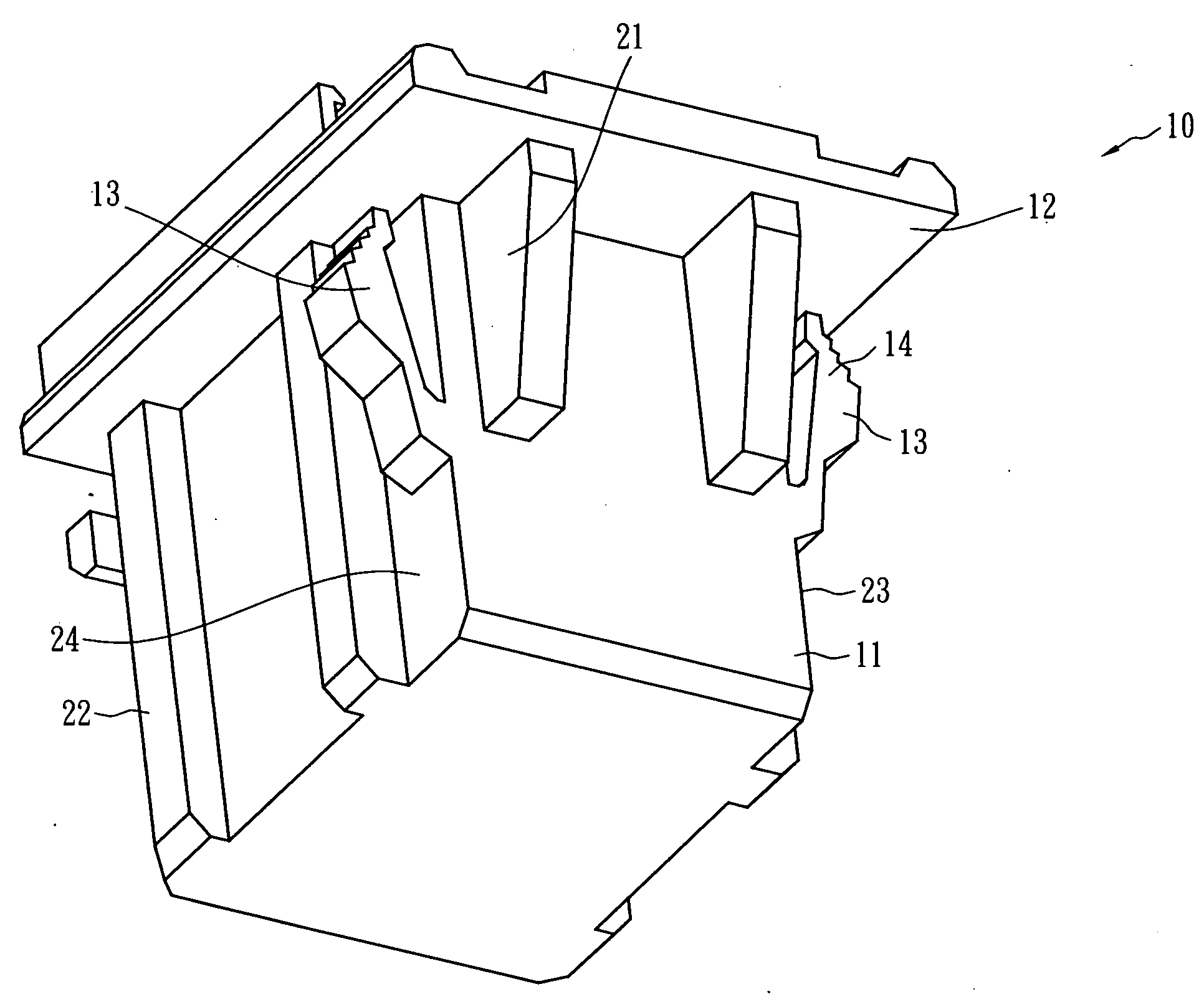
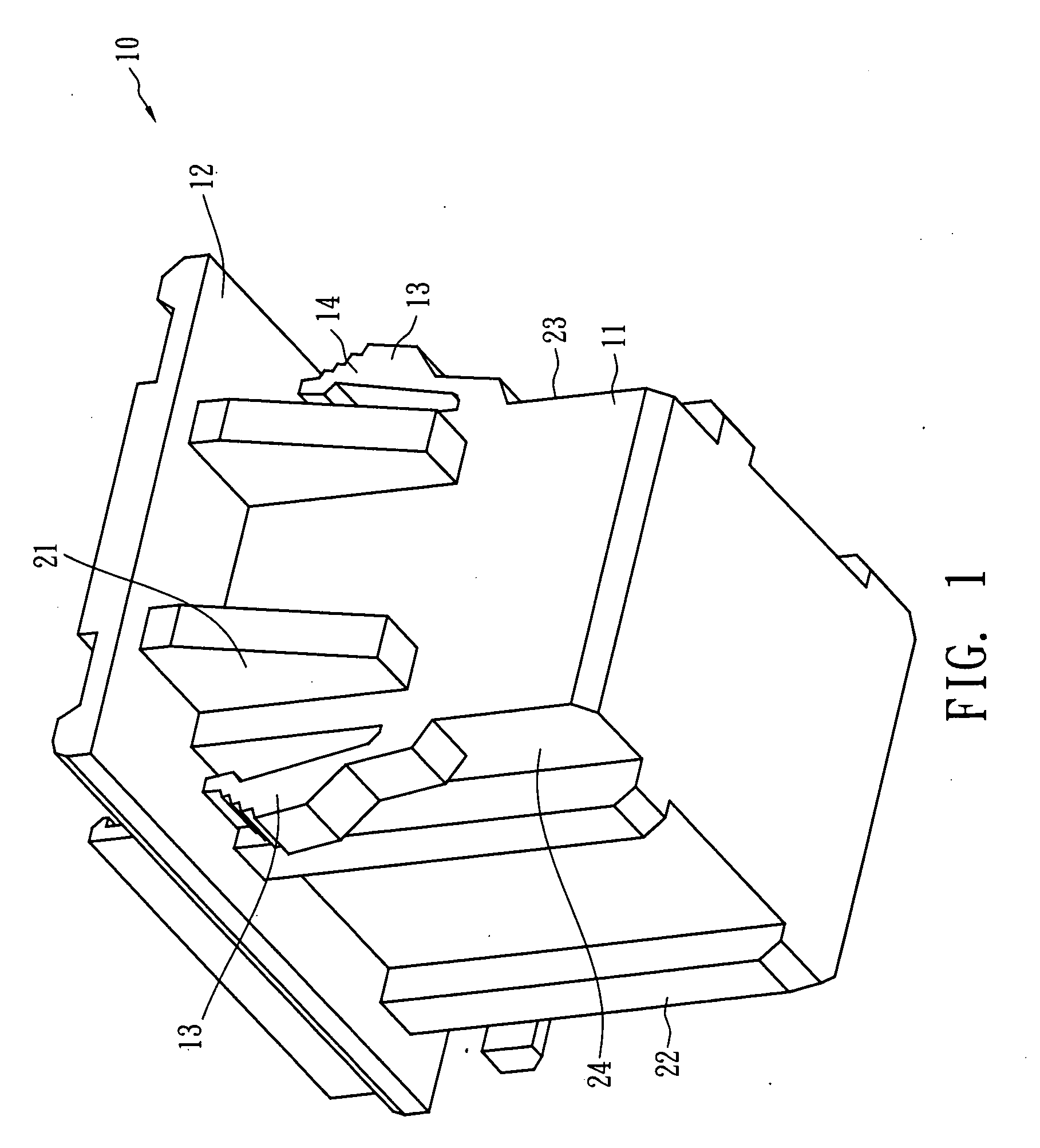
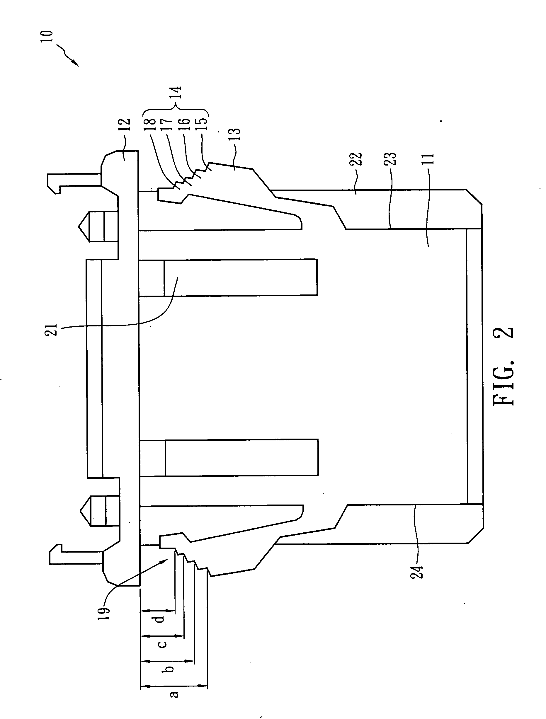
[0023]FIG. 1 illustrates a lamp socket in accordance with the present invention, and FIG. 2 and FIG. 3 illustrate the front view and side view of the lamp socket shown in FIG. 1. A lamp socket 10 includes a socket body 11, and the upper portion of the socket body 11 is provided with a flange 12 that is connected to the socket body 11 and horizontally protrudes from the socket body 11. Two support members 13 are connected to the socket body 11 and extend upward. In this embodiment, the socket body 11 includes a first side surface 23 and a second side surface 24 opposite to the first side surface 23. The two support members 13 are placed at the first side surface 23 and the second side surface 24, respectively.
[0024]As shown in FIG. 1 and FIG. 2, in this embodiment, the top of the support member 13 is a stepped structure 14 including a first step 15, a second step 16, a third step 17 and a fourth step 18. Accordingly, the gaps between the stepped structure 14 and the flange 12 corresp...
second embodiment
[0027]FIG. 5 illustrates the lamp socket in accordance with the present invention, and FIG. 6 illustrates the front view of the lamp socket shown in FIG. 5. A lamp socket 20 includes a socket body 11, and the upper portion of the socket body 11 is provided with a flange 12 connected to the socket body 11 and horizontally protruding from the socket body 11. Two support members 43 are connected to the socket body 11 and extend upward. In this embodiment, the socket body 11 includes a first side surface 23 and a second side surface 24 opposite to the first side surface 23. The two support members 43 are placed at the first side surface 23 and the second side surface 24, respectively.
[0028]As shown in FIG. 6, in this embodiment, the support member 43 is a forked structure, and includes at least a first branch 44 and a second branch 45. The gap between the top of the first branch 44 and the flange 12 corresponds to a first engaging width e, and the gap between the top of the second branc...
third embodiment
[0031]FIG. 7 illustrates a lamp socket in accordance with the present invention, in which the lamp socket is engaged with a bezel of a backlight unit. FIG. 8 and FIG. 9 illustrate the front view and the side view, respectively, of the lamp socket shown in FIG. 7. A backlight unit 90 includes a lamp socket 70 and a bezel 80. The lamp socket 70 includes a socket body 11, and the upper portion of the socket body 11 is provided with a flange 12 connected to the socket body 11 and horizontally protruding from the socket body 11. In this embodiment, the socket body 11 includes a first side surface 63, a second side surface 64 opposite to the first side surface 63, a third side surface 65 and a fourth side surface 66 opposite to the third side surface 65. As shown in FIG. 8 and FIG. 9, two support members 73 are placed at the first side surface 63 and the second side surface 64, respectively. The gap between the top of the support member 73 and the flange 12 forms an engaging groove 75 wit...
PUM
 Abstract
Description
Claims
Application Information