Method for molding fiber-reinforced plastic, and molding device for same

a molding device and fiber-reinforced plastic technology, applied in the direction of butter manufacturing, transportation and packaging, other domestic articles, etc., can solve the problems of deformation of the core 43/b>, reduce the manufacturing cost of the mold required for molding, and increase the internal pressure of the deformation mold , the effect of reducing the cost of the molded articl

Active Publication Date: 2015-07-02
MITSUBISHI CHEM CORP
View PDF7 Cites 15 Cited by
  • Summary
  • Abstract
  • Description
  • Claims
  • Application Information

AI Technical Summary

Benefits of technology

[0065]After a predetermined number of molded articles having desired shapes are manufactured in this manner, there is a changeover to manufacturing new molded articles having different shapes and structures. At this time, first, a new one-sided mold is prepared and the one-sided mold used before is detached from the molding machine to be replaced with the new one-sided mold. In the changeover, the replacement of the deforming mold is unnecessary. That is, the deforming mold is not replaced but is used as it is during the subsequent moldings. As described above, in the present invention, when only the one-sided mold is replaced among the pair of molds, subsequent molded articles having new shapes and structures can be molded. During the changeover of the molding, there is no need to prepare a pair of molds provided with new shapes needed in a conventional method. By preparing only a single one-sided mold, it becomes possible to mold a fiber-reinforced plastic molded article having an open cross-section with a new shape and a structure.
[0066]As a result, the manufacturing cost of the molds required for molding is reduced, and the cost of the molded article can be significantly reduced. Furthermore, during the pressure molding, on the opposite surface of the prepreg to the surface of the one-sided mold side, grains in the deforming mold freely flow due to external force (pressing force) and thus a necessary and sufficient pressing force can be exerted uniformly on every part of the surface. Moreover, even in a case the internal pressure of the deforming mold is increased by using auxiliary pressing means, for example, a rod material to be locally operated on a portion of the deforming mold, since surface pressure is always applied to the prepreg, the direction of the fiber included in the prepreg is not affected, and the manufacturing of a high-quality product is always guaranteed during molding of this type of fiber-reinforced plastic article which focuses on fiber direction.

Problems solved by technology

In addition, in a case a wide flat part is present as the shape of the core 43, the rigidity of the flat part is likely to be insufficient, and thus the core 43 may be deformed.

Method used


Image

  • Method for molding fiber-reinforced plastic, and molding device for same
  • Method for molding fiber-reinforced plastic, and molding device for same
  • Method for molding fiber-reinforced plastic, and molding device for same

Examples


example 1

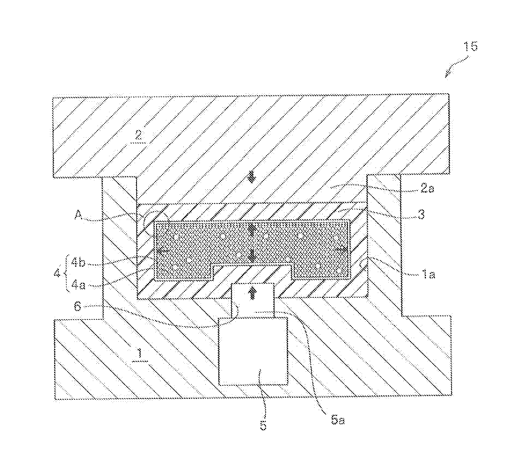
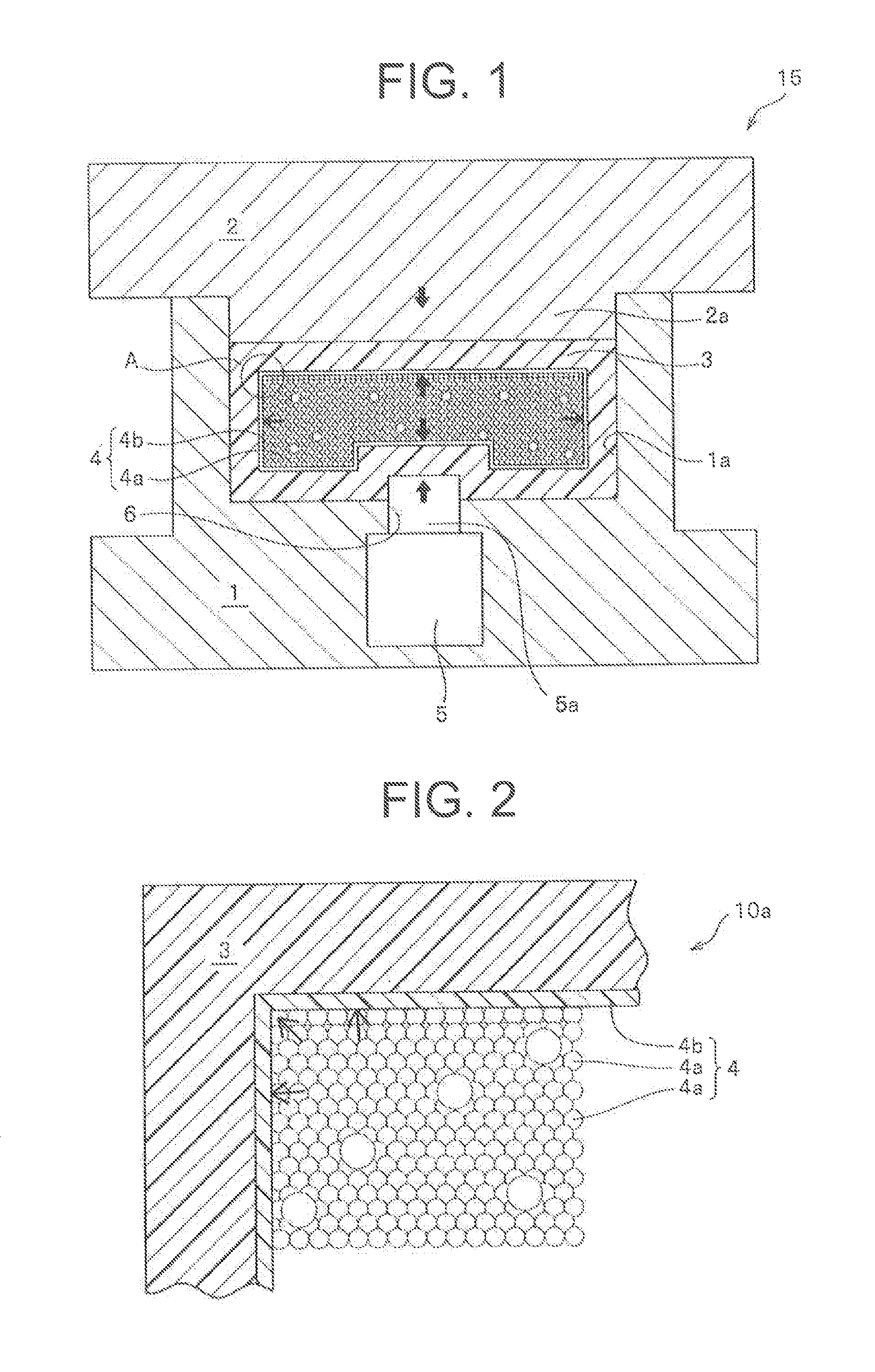
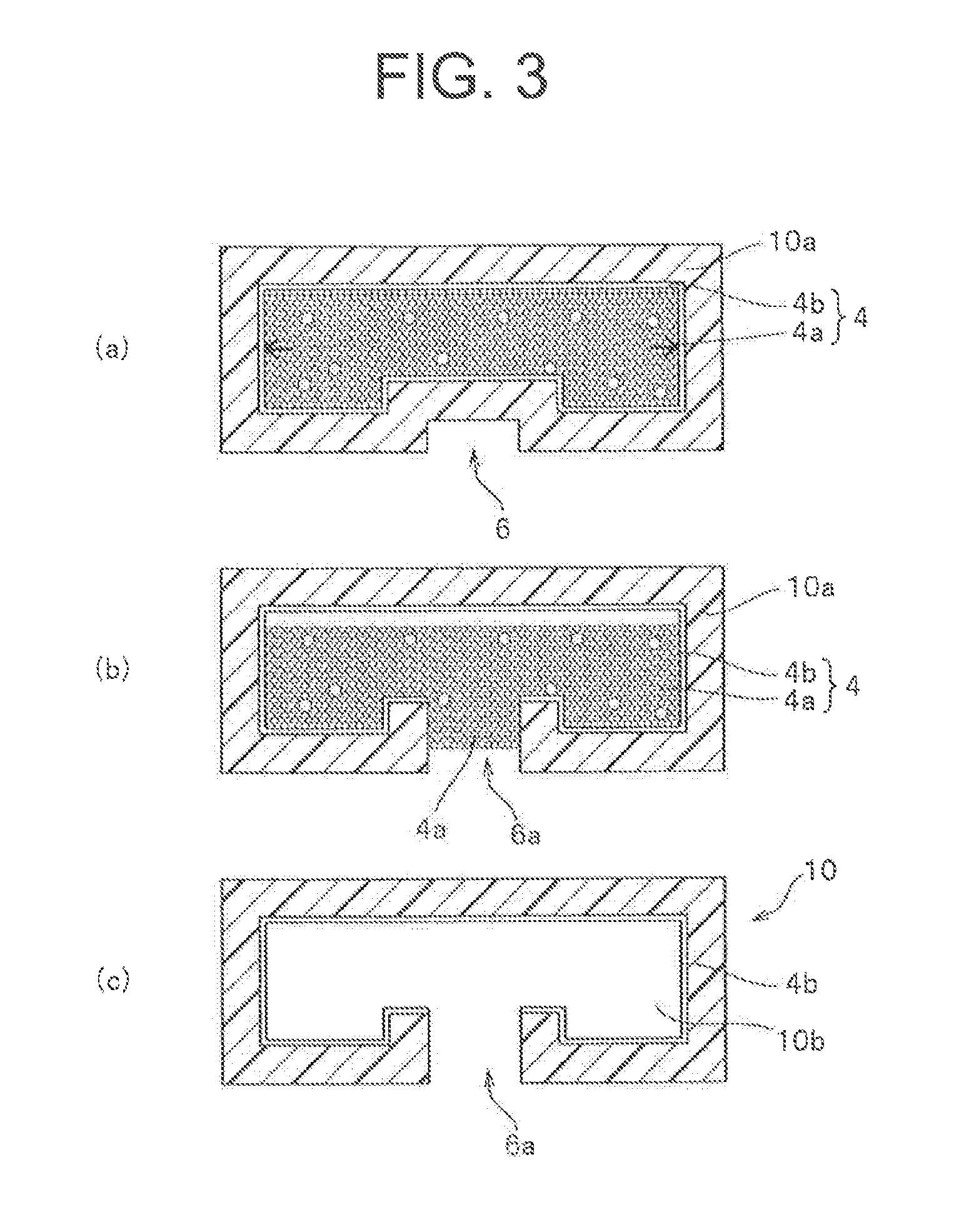
[0118]As illustrated in FIG. 1, a core was manufactured by accommodating a grain group which contained a mixture of zirconia grains (grains (a) having a diameter of 3 mm and grains (b) having a diameter of 2 mm) having the ratio of grain diameters equal to 1.5 and including 20 mass % of grains (b) as the ratio of the total amount of the grains (b) included in the mixture of zirconia grains (the mixing ratio of the grains (b)), in a bag made of a nylon film. The core was wrapped in five plies of prepreg 3 of a carbon fiber-reinforced epoxy resin (product name: TR3110 391IMU, made by Mitsubishi Rayon Co., Ltd.) to make a preform having substantially the same shape as the inner circumferential surface shape of the molding die 15 at room temperature. The preform was placed in the concave portion 1a formed in the molding surface of the lower mold 1 of the molding die 15 heated to 140° C. in advance, and the upper mold 2 and the lower mold 1 were completely closed. Subsequently, a portion...

examples 2 to 4

[0119]Hollow molded articles (FIG. 3(c)) were obtained in the same manner as Example 1 except that the mixing ratios of the zirconia grains (b) included in the grain group 4a of the core 4 were as shown in Table 1.

modification example 1

[0125]While the upper mold 2 and the lower mold 1 are in a state of being closed to each other, or while the prepreg 3 is in a pressurized state of being pressurized by the upper mold 2 and the lower mold 1 at a predetermined pressure, the interval between the upper mold 2 and the lower mold 1 should not increase any more. Therefore, according to the illustrated examples, mold interval holding means 20 for maintaining the interval between the upper and lower molds 2 and 1 in a constant level are provided in the upper mold 2. As illustrated in FIG. 4, as the mold interval holding means 20, a configuration is employed in which the upper mold 2 is not raised by an increase in the pressing force to the upper mold 2 due to the deformation of the prepreg 3 even when the core 4 is pressed and deformed by the piston rod 5a.

[0126]In the example illustrated in FIGS. 4 and 7(A), the mold interval holding means 20 include wedge surfaces 21b and 21b which comes in sliding contact with downward ...


PUM

PropertyMeasurementUnit
flexural modulusaaaaaaaaaa
thicknessaaaaaaaaaa

Abstract

A method for molding fiber-reinforced plastic. A core is formed in a desired shape by accommodating, in a flexible bag, a grain group containing plurality of grains. The core is placed inside a prepreg containing resin and fibers, and the prepreg, in which the core is housed is placed in a molding die and compression molded. When doing so, the grain group contains first and second grains (a,b) that satisfy the equation (1). (1) 1.1≦(Da/Db)≦2.0 In the equation Da is the grain diameter of the grains (a), and Db is the grain diameter of the grain (b). When using a molding die to mold a molded article having a cavity, the above mentioned molding method enables an increase in the internal pressure of the core in order to change the peripheral surface area of the core, without using a pressurized gas and/or pressurized liquid.

Description

TECHNICAL FIELD[0001]The present invention relates to a molding method and a molding device for manufacturing a molded article of a fiber-reinforced plastic having a closed cross-section by using a core and by heating and pressurizing a prepreg made by impregnating fiber with a resin.BACKGROUND ART[0002]A fiber-reinforced plastic molded article having a closed cross-section is widely used in a range from large molded articles such as the body or wings of an aircraft to small molded articles such as a bicycle frame, a tennis racket, a fishing rod, and a golf shaft. In addition, a fiber-reinforced plastic molded article having an open cross-section is widely used for helmets and the like.[0003]As a core for forming the closed cross-section, a core formed into a predetermined shape by wrapping a group of powder particles and / or a group of grains (hereinafter, a powder grain group) in a packaging film and vacuum-packaging the result, a core using a molded product formed by blow molding,...

Claims


Application Information

Patent Timeline
Patent Type & Authority Applications(United States)
IPC IPC(8): B29C43/18B29C70/02
CPCB29C43/18B29L2031/00B29C70/021B29C33/54B29C43/10B29C43/36B29C43/3642B29C70/44B29C70/46B29C2043/3222B29C2043/3655B29C2043/3649B29C2043/3665B29C2043/106B29K2105/0872B29K2105/12B29L2022/00B60B5/02B29C2043/3613B29C70/461B29C70/28B29C70/50
Inventor TAKANO, TSUNEOKAZEHAYA, YUUJINISHIMURA, MITSUSHI
Owner MITSUBISHI CHEM CORP
Why Eureka
Try Eureka