
Valve for regulating fluids

a valve and fluid technology, applied in the direction of valve operating means/release devices, fuel injecting pumps, machines/engines, etc., can solve the problems of correspondingly large, cost-intensive piezoelectric unit dimensioning, adversely affecting the opening behavior of the entire valv

Inactive Publication Date: 2003-12-02
ROBERT BOSCH GMBH
View PDF9 Cites 3 Cited by
  • Summary
  • Abstract
  • Description
  • Claims
  • Application Information

AI Technical Summary

Benefits of technology

This solution reduces the required actuator force and allows for precise preinjection quantity control without replacing parts, improving valve opening behavior and reducing costs by utilizing a smaller piezoelectric unit and faster refilling times.

Problems solved by technology

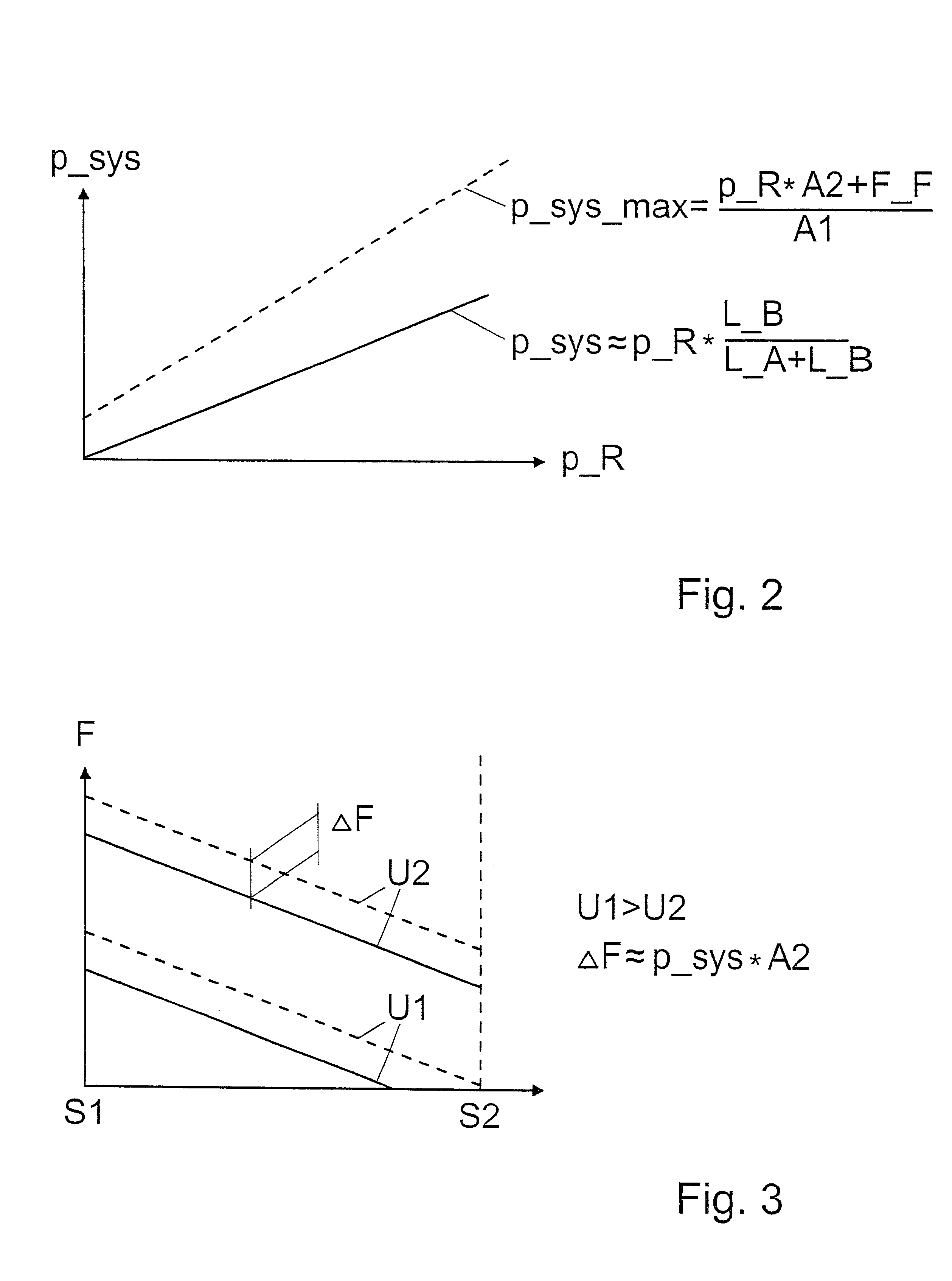
However, if the system pressure in the hydraulic chamber is substantially constant, and is at least largely independent of the prevailing high pressure in the high-pressure region, there is the problem that at high pressure values, great actuator force is required to open the valve closing member counter to the high-pressure direction, which in turn dictates a correspondingly large, cost-intensive dimensioning of the piezoelectric unit.
Moreover, at high pressure in the high-pressure region, the positive displacement of hydraulic volume out of the hydraulic chamber via the gaps surrounding the adjacent pistons is reinforced accordingly, meaning that under some circumstances, the refilling time for building up and maintaining the counterpressure on the low-pressure region is prolonged, so that for lack of complete refilling, in the event of a re-actuation of the valve soon thereafter, a shorter valve stroke will be executed, which can adversely affect the opening behavior of the entire valve.

Method used


Image

  • Valve for regulating fluids
  • Valve for regulating fluids
  • Valve for regulating fluids

Examples


Embodiment Construction

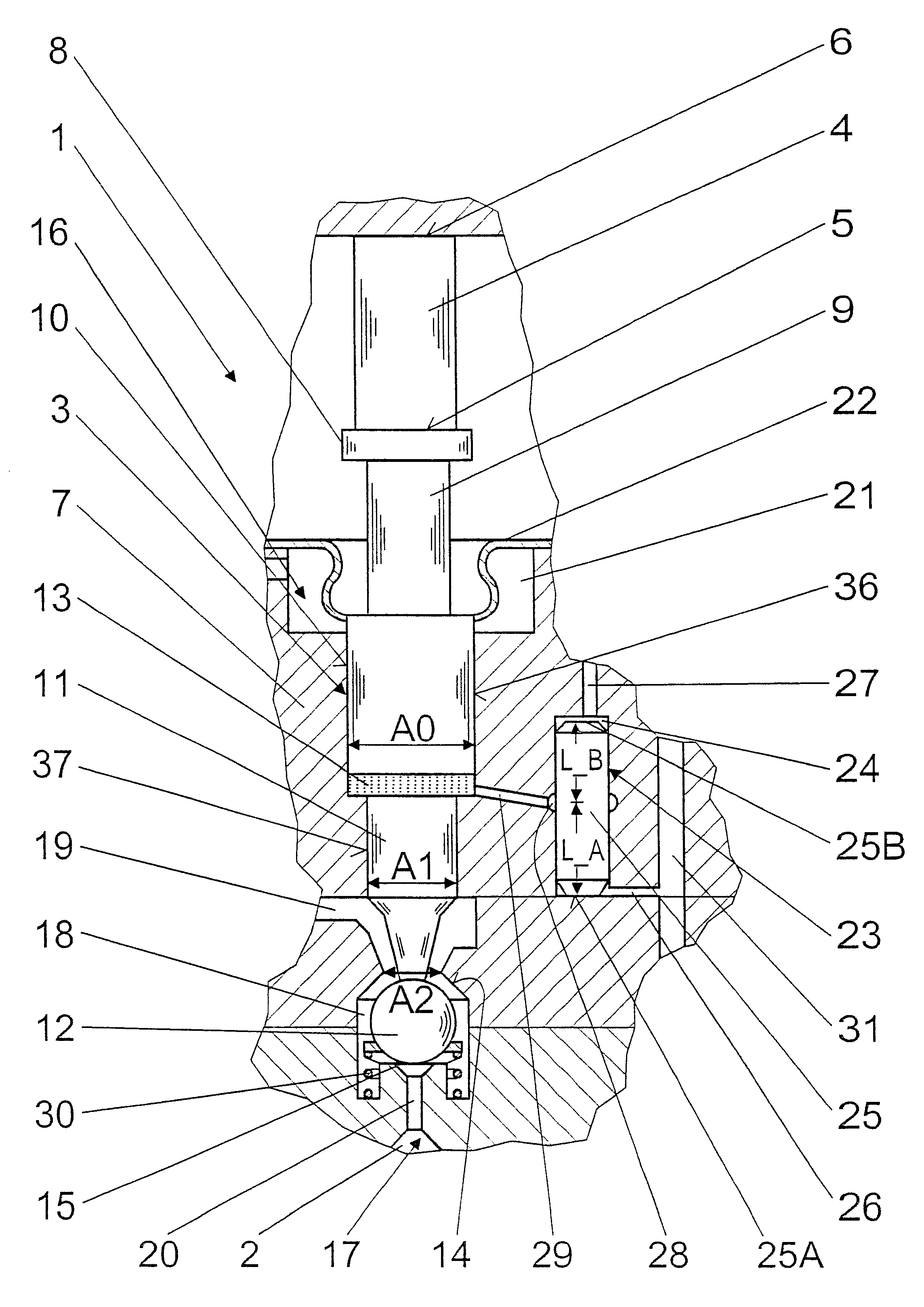
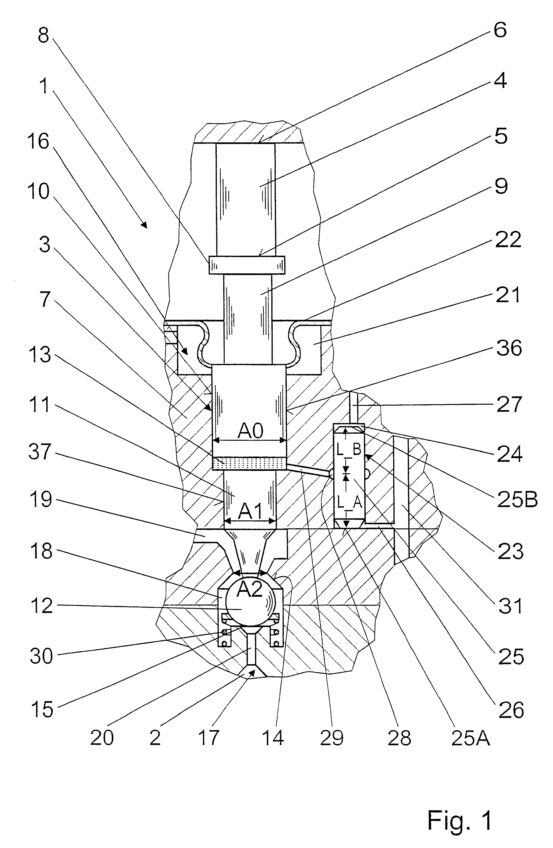
The exemplary embodiment shown in FIG. 1 illustrates a use of the valve of the invention in a fuel injection valve 1 for internal combustion engines of motor vehicles. In the present embodiment, the fuel injection valve 1 is embodied as a common rail injector for injecting Diesel fuel; the fuel injection is controlled via the pressure level in a valve control chamber 2, which communicates with a supply of high pressure.

For adjusting the injection onset, a duration of injection, and an injection quantity via force ratios in the fuel injection valve 1, a valve member 3 is triggered via a piezoelectric unit embodied as a piezoelectric actuator 4, which is disposed on the side of the valve member 3 remote from the valve control chamber and from the combustion chamber. The piezoelectric actuator 4 is constructed in the usual way in a plurality of layers, and on its side toward the valve member 3, it has an actuator head 5, while on its side remote from the valve member 3 it has an actuat...


PUM


Abstract

The invention relates to a valve for controlling fluids, having a piezoelectric unit (4) for actuating a valve member (3), with which a valve closing member (12) is associated that divides a low-pressure region (16) at system pressure from a high-pressure region (17). The valve member (3) has at least one first piston (9) and one second piston (11), between which a hydraulic chamber (13) is embodied. To compensate for leakage losses, a filling device (23) is used, which can communicate with the high-pressure region (17) and which has at least one channel-like hollow chamber (24), in which a solid body (25) is disposed, with a gap surrounding it, in such a way that on one end (25A) of the solid body (25), a line (26) branching off from the high-pressure region (17), and on its opposite end (25B) a leakage line (27) discharges into the hollow chamber (24), and that a line (29) leading to the hydraulic chamber (13) branches off along the length of the solid body (25), and the system pressure (p_sys) in the hydraulic chamber (13) is adjustable by geometric definition of the branching point (28) (FIG. 1).

Description

PRIOR ARTThe invention is based on a valve for controlling fluids in accordance with the type defined in further detail in claim 1.Such valves for controlling fluids, in which a valve closing member divides a low-pressure region in the valve from a high-pressure region, are well known in the industry, for example in fuel injectors, especially common rail injectors, or in pumps of motor vehicles.European Patent Disclosure EP 0 477 400 A1 also describes such a valve; it is actuatable via a piezoelectric actuator and has an arrangement for a travel converter, acting in the stroke direction, of the piezoelectric actuator; the deflection of the actuator is transmitted via a hydraulic chamber, which serves as a hydraulic booster or coupling and as a tolerance compensation element. The hydraulic chamber encloses a common compensation volume between two pistons defining the hydraulic chamber, of which one piston is embodied with a smaller diameter and is connected to a valve closing member ...

Claims


Application Information

Patent Timeline
Patent Type & Authority Patents(United States)
IPC IPC(8): F02M59/00F02M59/46F02M47/02F02M47/00F02M51/00F02M51/06
CPCF02M47/027F02M63/0026F02M63/0045F02M63/0036F02M2200/705
Inventor STOECKLEIN, WOLFGANGSCHMIEDER, DIETMAR
Owner ROBERT BOSCH GMBH
Learn More