Center pipe for plasma torch, contact piece, electrode, and plasma torch

a plasma torch and center pipe technology, applied in plasma welding apparatus, plasma technique, manufacturing tools, etc., can solve the problems of needing to replace the torch body of the plasma torch, complex etc., and achieve the effect of easy attachment and removal, simplified structure of the electrode or the electrode sea

Active Publication Date: 2019-03-19
KOMATSU IND CORP
View PDF20 Cites 5 Cited by
  • Summary
  • Abstract
  • Description
  • Claims
  • Application Information

AI Technical Summary

Benefits of technology

[0025]The contact piece of the center pipe energizes the electrode by being in contact with the internal circumferential surface of the electrode in the present invention. Therefore, a structure for connecting the base end side cylindrical portion of the electrode and the internal circumferential surface of the electrode seat as described above is made unnecessary. As a result, the structure of the electrode or of the electrode seat can be simplified. Moreover, the electrode can be attached and detached easily without a specialized tool by making the abovementioned thread structure unnecessary. Furthermore, replacement of the torch body is unnecessary even when an energization fault occurs.

Problems solved by technology

There is a problem in that the structure of the electrode or of the electrode seat is complex in order for the base end side cylindrical portion and the internal circumferential surface of the electrode seat to be connected in the abovementioned plasma torch.
Furthermore, there is a problem that the torch body of the plasma torch needs to be replaced if the energization surfaces of the base end side cylindrical portion and the electrode seat are damaged due to energization fault.

Method used


Image

  • Center pipe for plasma torch, contact piece, electrode, and plasma torch
  • Center pipe for plasma torch, contact piece, electrode, and plasma torch
  • Center pipe for plasma torch, contact piece, electrode, and plasma torch

Examples


first embodiment

[0064]Plasma Torch Configuration

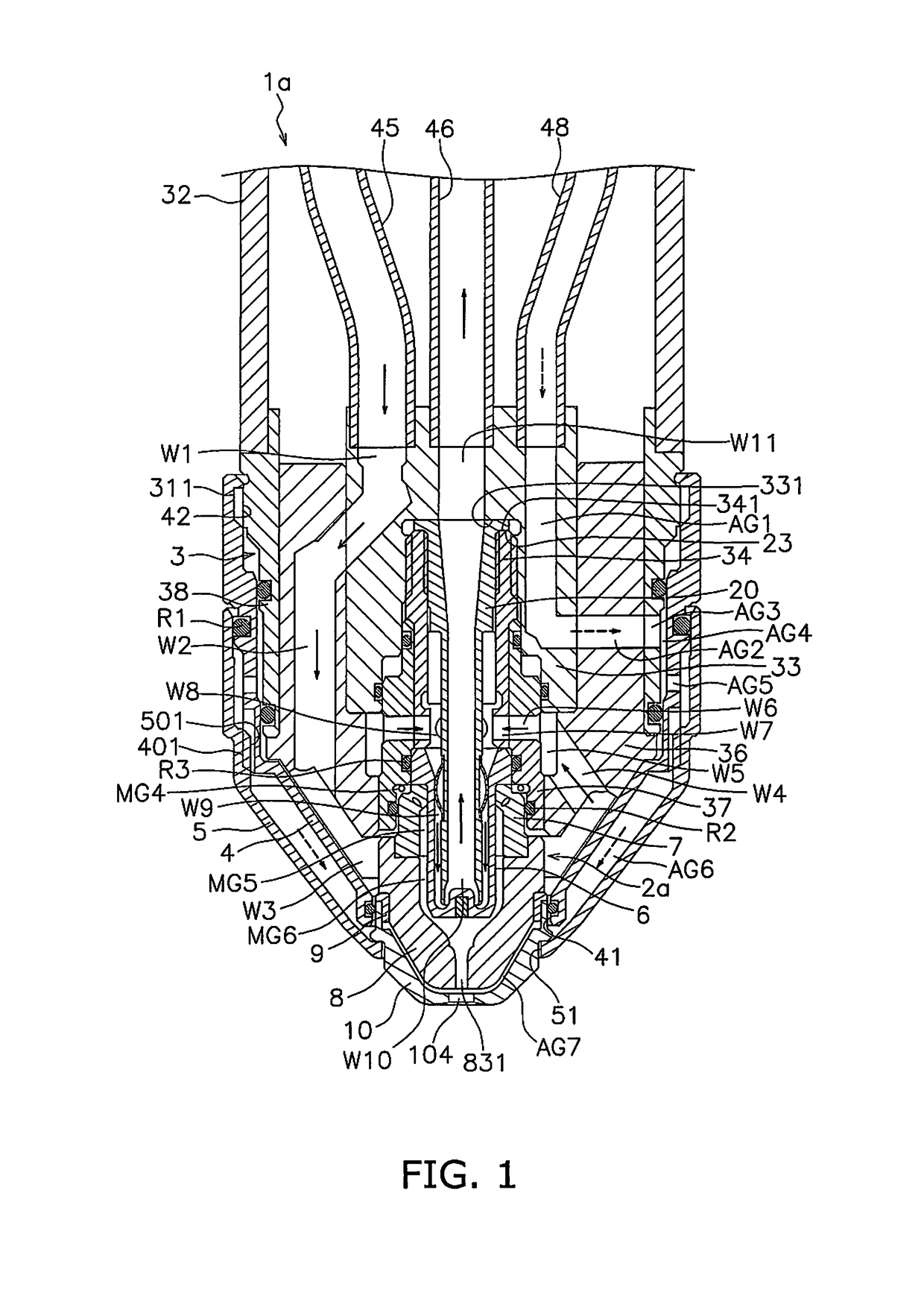
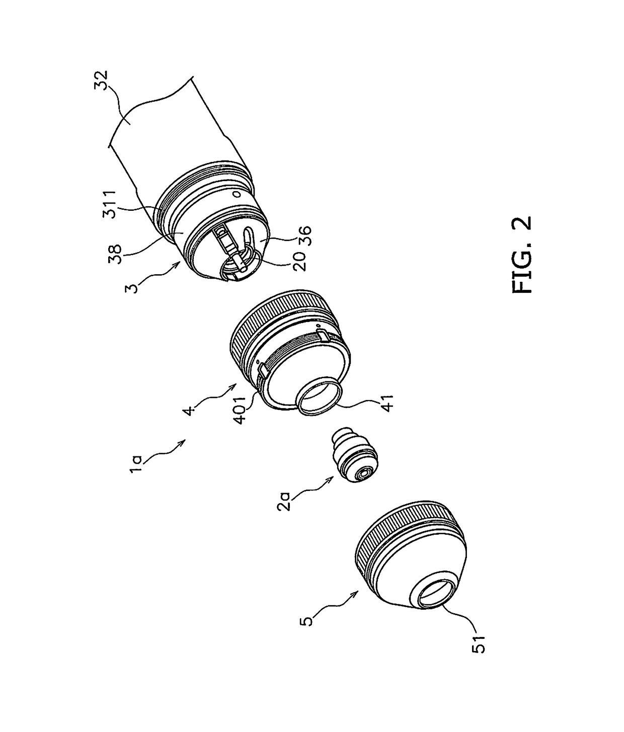
[0065]A plasma torch according to the embodiments will be discussed below with reference to the drawings. FIG. 1 is a cross-sectional view along the center axis of a plasma torch 1a according to a first embodiment. FIG. 2 is an exploded view of the plasma torch 1a. The plasma torch 1a according to the present embodiment is a plasma torch 1a for oxygen plasma cutting. However, the plasma torch 1a may be a plasma torch for plasma cutting using a gas that does not include oxygen such as nitrogen or argon.

[0066]As illustrated in FIG. 2, the plasma torch 1a includes a replacement part unit 2a, a torch body 3, a first retainer cap 4 and a second retainer cap 5. The replacement part unit 2a, the first retainer cap 4, and the second retainer cap 5 are disposed concentrically on the center axis of the torch body 3.

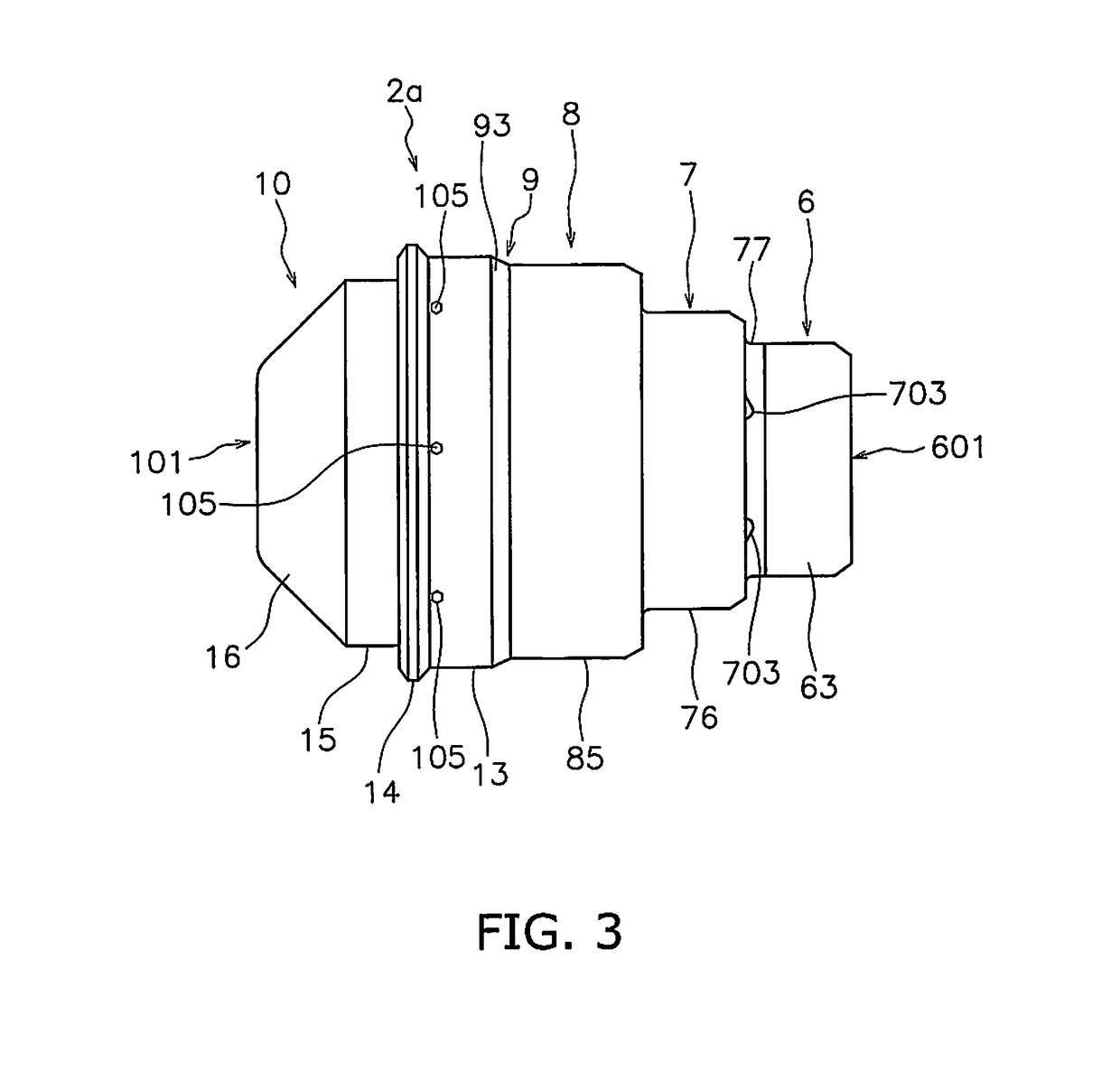
[0067]As illustrated in FIG. 1, the replacement part unit 2a is attached to the torch body 3. The replacement part unit 2a includes an electrode 6, ...

second embodiment

2. Second Embodiment

[0183]A plasma torch 1b as in a second embodiment will be discussed next. FIG. 32 is a cross-sectional view along the center axis of the plasma torch 1b according to the second embodiment. FIG. 33 is a cross-sectional view of the replacement part unit 2b according to the second embodiment. FIGS. 34 and 35 are perspective views of the replacement part unit 2b. FIGS. 36 and 37 are perspective views of the nozzle 8 according to the second embodiment.

[0184]As illustrated in FIG. 33, the first external circumferential surface 85 of the nozzle 8 includes a recessed portion 851. The recessed portion 851 is provided on the second nozzle portion 82. The recessed portion 851 is recessed toward the inside in the radial direction of the nozzle 8 and extends in the circumferential direction of the nozzle 8. The recessed portion 851 is disposed at approximately the same position as the tip end of the electrode 6 in the axial direction of the nozzle 8. The outer diameter of the...


PUM

PropertyMeasurementUnit
temperatureaaaaaaaaaa
inclination angleaaaaaaaaaa

Abstract

A center pipe is used in a plasma torch for plasma cutting including a base portion and an electrode. The center pipe is inserted into the electrode and supplies cooling water into the electrode. The center pipe includes a pipe body and a contact piece. The pipe body is electrically connected to an electrical power source outside of the plasma torch via the base portion. The pipe body includes a cooling water channel therein. The pipe body is formed with an electrically conductive body. The contact piece is provided on the external circumferential surface of the pipe body and energizes the electrode through contact with the internal circumferential surface of the electrode. The contact piece has elasticity to produce a counterforce when pressed in the radial direction of the pipe body. The contact piece is formed with an electrically conductive body.

Description

CROSS-REFERENCE TO RELATED APPLICATIONS[0001]This application is a U.S. National stage application of International Application No. PCT / JP2015 / 084161, filed on Dec. 4, 2015. This U.S. National stage application claims priority under 35 U.S.C. § 119(a) to Japanese Patent Application No. 2015-017463, filed in Japan on Jan. 30, 2015, the entire contents of which are hereby incorporated herein by reference.BACKGROUND[0002]Field of the Invention[0003]The present invention relates to a center pipe for a plasma torch, a contact piece, an electrode, and a plasma torch.[0004]Background Information[0005]A plasma torch includes an electrode that acts as the originating point of an arc, and a nozzle disposed so as to cover the electrode. The electrode is attached to an electrode seat of a torch body. The nozzle is attached to the electrode via an insulation guide. The insulation guide positions the nozzle so that the nozzle is disposed concentrically with the electrode. The plasma torch causes ...

Claims


Application Information

Patent Timeline
Patent Type & Authority Patents(United States)
IPC IPC(8): B23K10/00H05H1/34H05H1/28
CPCB23K10/00H05H1/28H05H1/34H05H2001/3457H05H2001/3436H05H1/3436H05H1/3457H05H1/3423
Inventor YAMAGUCHI, YOSHIHIROKONDO, KEITAMORIMOTO, SHIGEOSAIO, KATSUO
Owner KOMATSU IND CORP
Why Eureka
Try Eureka