Brushless wiper motor

a technology of wiper motor and brushless, which is applied in the direction of vehicle maintenance, vehicle cleaning, transportation and packaging, etc., can solve the problems that its size and weight reduction may be reaching its limits, and achieve the effect of improving in silen

Active Publication Date: 2020-10-06
MITSUBA CORP
View PDF37 Cites 5 Cited by
  • Summary
  • Abstract
  • Description
  • Claims
  • Application Information

AI Technical Summary

Benefits of technology

[0005]In addition, since wiper motors are mounted on a wide variety of vehicles including a kei car (small-sized vehicle) and a large-sized vehicle. Therefore, it is necessary to further reduce its size and weight to enhance versatility. Furthermore, in recent vehicles or the like, various control devices are provided inside its instrument panel or the like positioned close to the wiper motor. Therefore, it is necessary to suppress electric noises during operation to a maximum extent, and to prevent the control devices from malfunctioning.
[0007]An object of the present invention is to provide a brushless wiper motor improved in size and weight while suppressing electric noises, and enabling stable operation with low electric power.
[0017]Therefore, since it is unnecessary to provide a coil, a commutator or the like at the free end portion of the rotation shaft which is not supported at all, while the rotation shaft is shortened as compared with the conventional one, an inertial mass of the free end portion of the rotation shaft can be made small. Therefore, the rotation shaft can be caused to act stably as compared with the conventional one, and improvement in silence can be achieved. Furthermore, since the commutator and the brush are not provided, occurrence of electric noises is suppressed, so that while adverse effect to the control devices is removed, brush replacement is made unnecessary to achieve maintenance free.

Problems solved by technology

Furthermore, since the wiper motor has a brush unit, electric noise countermeasure is required for electric noises, and its size and weight reductions may be reaching their limits.
Furthermore, since the commutator and the brush are not provided, occurrence of electric noises is suppressed, so that while adverse effect to the control devices is removed, brush replacement is made unnecessary to achieve maintenance free.

Method used


Image

  • Brushless wiper motor
  • Brushless wiper motor
  • Brushless wiper motor

Examples


first embodiment

[0034]Hereinafter, the present invention will be described with reference to the accompanying drawings.

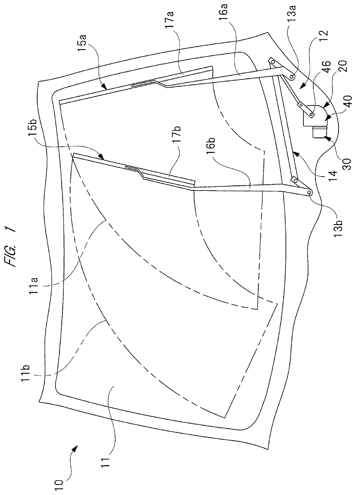
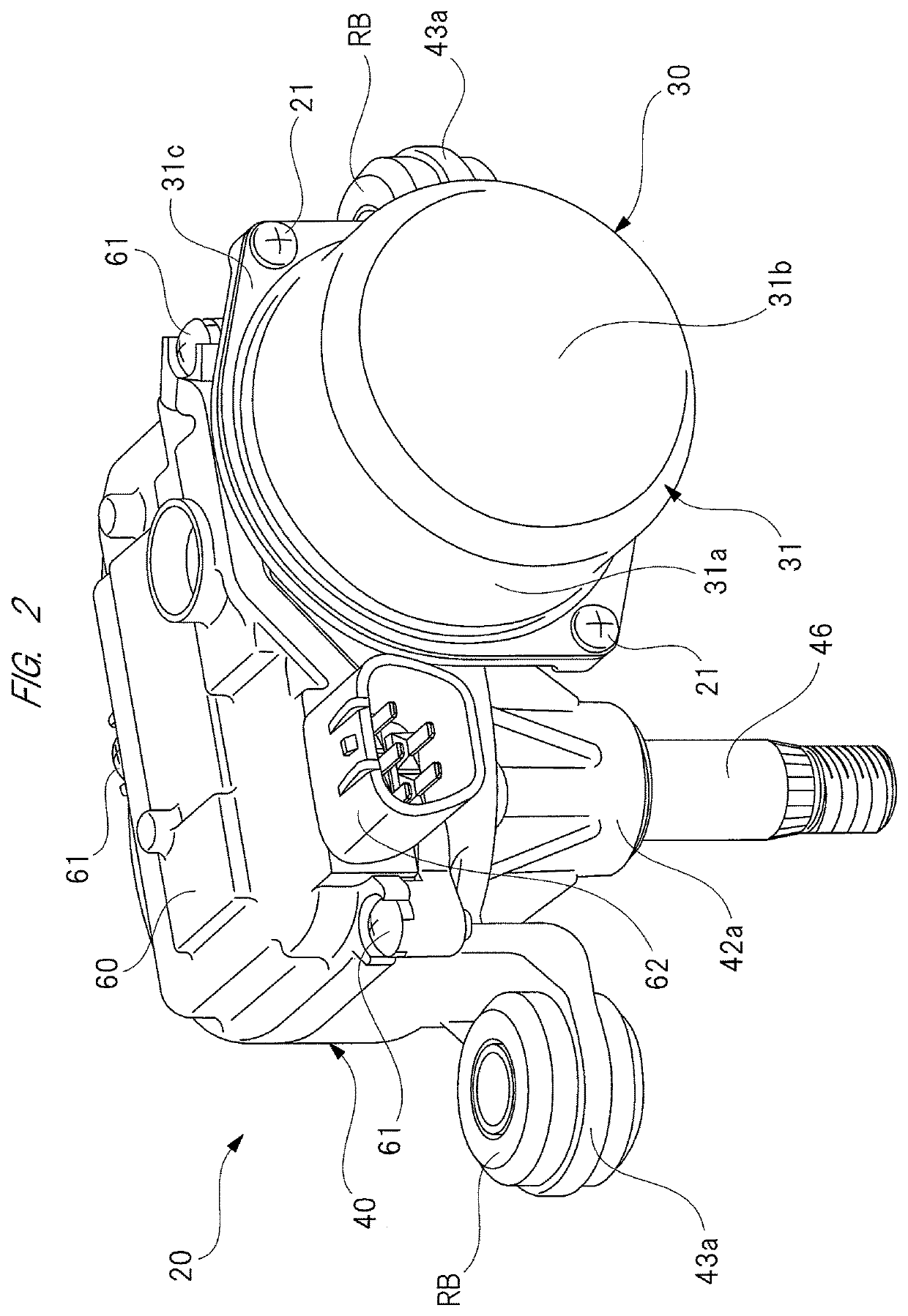
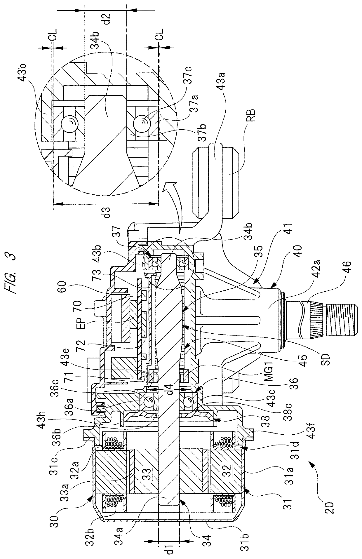
[0035]FIG. 1 is a view showing a wiper apparatus mounted on a vehicle, and provided with a brushless wiper motor according to the present invention; FIG. 2 is a perspective view of the brushless wiper motor, viewed from a motor unit; FIG. 3 is a sectional view explaining an internal structure of the brushless wiper motor; FIG. 4 is a perspective view showing a rotor unit; FIG. 5A is a perspective view of a stopper spring; FIG. 5B is a sectional view of the stopper spring; FIG. 6 is a perspective view explaining a detailed structure of a gear case; FIG. 7 is a perspective view showing a worm wheel unit; and FIG. 8 is a perspective view explaining a detailed structure of a gear cover.

[0036]As shown in FIG. 1, a front windshield 11 is provided on a vehicle 10 such as automotive vehicle. A wiper apparatus 12 is mounted on a front end portion of the front windshield 11 in the vehicle 10...

second embodiment

[0097]FIG. 12 is a perspective view explaining a casing and a cover member of a brushless wiper motor according to a

[0098]In the above-described first embodiment, as shown in FIG. 3, the motor unit 30 and the gear unit 40 are constituted as discrete members, and the motor case 31 and the gear case 41 are respectively coupled to each other. On the other hand, in a brushless wiper motor 90 according to the second embodiment, as shown in FIG. 12, a casing 91 having a motor case portion 92 and a gear case portion 93 integrated with each other is adopted.

[0099]Specifically, the casing 91 is formed into a predetermined shape by casting aluminum material or the like, and the gear case portion 93 is formed into a shape approximately similar to that of the gear case 41 (see FIG. 6) of the first embodiment. Therefore, detailed explanation of the gear case 93 is omitted.

[0100]On the other hand, the motor case portion 92 is provided with a cylindrical main body portion 94 having a small diamete...

third embodiment

[0111]FIG. 13 is an explanatory view of a brushless wiper motor of a third embodiment corresponding to FIG. 9, and FIG. 14 is a partial sectional view of the brushless wiper motor of FIG. 13, taken along an axial direction of a rotation shaft.

[0112]As shown in FIGS. 13 and 14, a brushless wiper motor 100 according to the third embodiment is different from that of the first embodiment in structure of a rotor unit 101 and assembling procedure of the rotor unit 101 to a gear case (casing) 102. More specifically, in the first embodiment, as shown in FIG. 9, the rotor unit RU is fixed to the gear case 41 by integrally providing the annular stopper spring 38 and the rotor unit RU with each other in advance, and press-fitting the stopper spring 38 into the spring receiving portion 43h while attaching the first ball bearing 36 to the first bearing attaching portion 43d.

[0113]On the other hand, in the third embodiment, as shown in FIGS. 13 and 14, by using a stopper member 103 separated fro...


PUM


Abstract

In a brushless wiper motor, a rotor (33) is rotatably provided inside a stator (32) provided with a coil (32b), one end side of a rotation shaft (34) in the axial direction is fixed to the axial center of the rotor (33), a worm (35) is provided on the other end side of the rotation shaft (34) in the axial direction, the first and second bearings (36, 37) are respectively provided on one end side of the rotation shaft (34) in the axial direction and the other end side of the rotation shaft (34) in the axial direction than the worm (35) of the rotation shaft (34), the rotation shaft (34) is rotatably supported by only the first and second bearings (36, 37), and with the position of the first bearing (36) being defined as a reference position, a length thereof in the axial direction to the second bearing (37) is longer than a length thereof in the axial direction to the rotor (33). Since a commutator and other parts are not provided on a free end side of the rotation shaft (34), it is possible to provide a brushless wiper motor reduced in length of the rotation shaft (34), and reduced in inertial mass of the free end side of the rotation shaft (34).

Description

CROSS-REFERENCE TO RELATED APPLICATION[0001]Applicant hereby claims foreign priority benefits under U.S.C. § 119 from International Patent Application Serial No. PCT / JP2015 / 070110 filed on Jul. 14, 2015 and Japanese Patent Application No. 2014-145163 filed Jul. 15, 2014, the contents of all of which are incorporated by reference herein.TECHNICAL FIELD[0002]The present invention relates to a brushless wiper motor which swings a wiper member provided on a windshield.BACKGROUND ART[0003]Conventionally, a wiper apparatus for wiping rain water, dust and the like on a windshield is mounted on a vehicle such as automotive vehicle. The wiper apparatus is provided with: a wiper member provided on a windshield; and a wiper motor for swinging the wiper member. By ON-operation of a wiper switch provided within a vehicle compartment, the wiper motor is rotated so that the wiper member is swung on the windshield. Since the wiper motor is provided in a small mounting space closed by a cowl top pan...

Claims


Application Information

Patent Timeline
Patent Type & Authority Patents(United States)
IPC IPC(8): H02K7/11H02K7/116B60S1/08H02K29/08H02K7/08H02K11/215H02K5/15H02K5/16
CPCH02K29/08H02K7/1166H02K7/116B60S1/08H02K7/08H02K11/215H02K7/081H02K5/16H02K5/15
Inventor SHODA, HIROKAZUISO, YUKIYOSHINAKAMURA, OSAMU
Owner MITSUBA CORP
Why Eureka
Try Eureka