Structure for mounting batteries onto electric vehicles

a technology for electric vehicles and structures, applied in the direction of cell components, cell components, propulsion by batteries/cells, etc., can solve the problems of difficult to bend such thick cables, damage to thick cables, and inability to adopt techniques, etc., to achieve the effect of simplifying the installation of high-voltage cables

Active Publication Date: 2010-07-06
MITSUBISHI MOTORS CORP
View PDF10 Cites 37 Cited by
  • Summary
  • Abstract
  • Description
  • Claims
  • Application Information

AI Technical Summary

Benefits of technology

[0011]The present invention has been developed in consideration of this situation, and it is therefore an object of the invention to provide a structure for mounting a battery onto an electric vehicle to utilize limited space in the electric vehicle and simplify installation of high-voltage cables connected to batteries mounted on the electric vehicle.

Problems solved by technology

However, in some situations, it is impossible to adopt the technique disclosed in the related document 1 of installing the cables through the front end of the battery box (9).
However, it is difficult to bend such thick cables.
For example, thick cables may be damaged if the cables are bent too much.
Conversely, it is impossible to utilize limited space in a vehicle if the cables are insufficiently bent in order to prevent damage to the cables.

Method used


Image

  • Structure for mounting batteries onto electric vehicles
  • Structure for mounting batteries onto electric vehicles
  • Structure for mounting batteries onto electric vehicles

Examples


Embodiment Construction

[0036]The embodiment of the present invention will now be described with reference to the accompanying drawings.

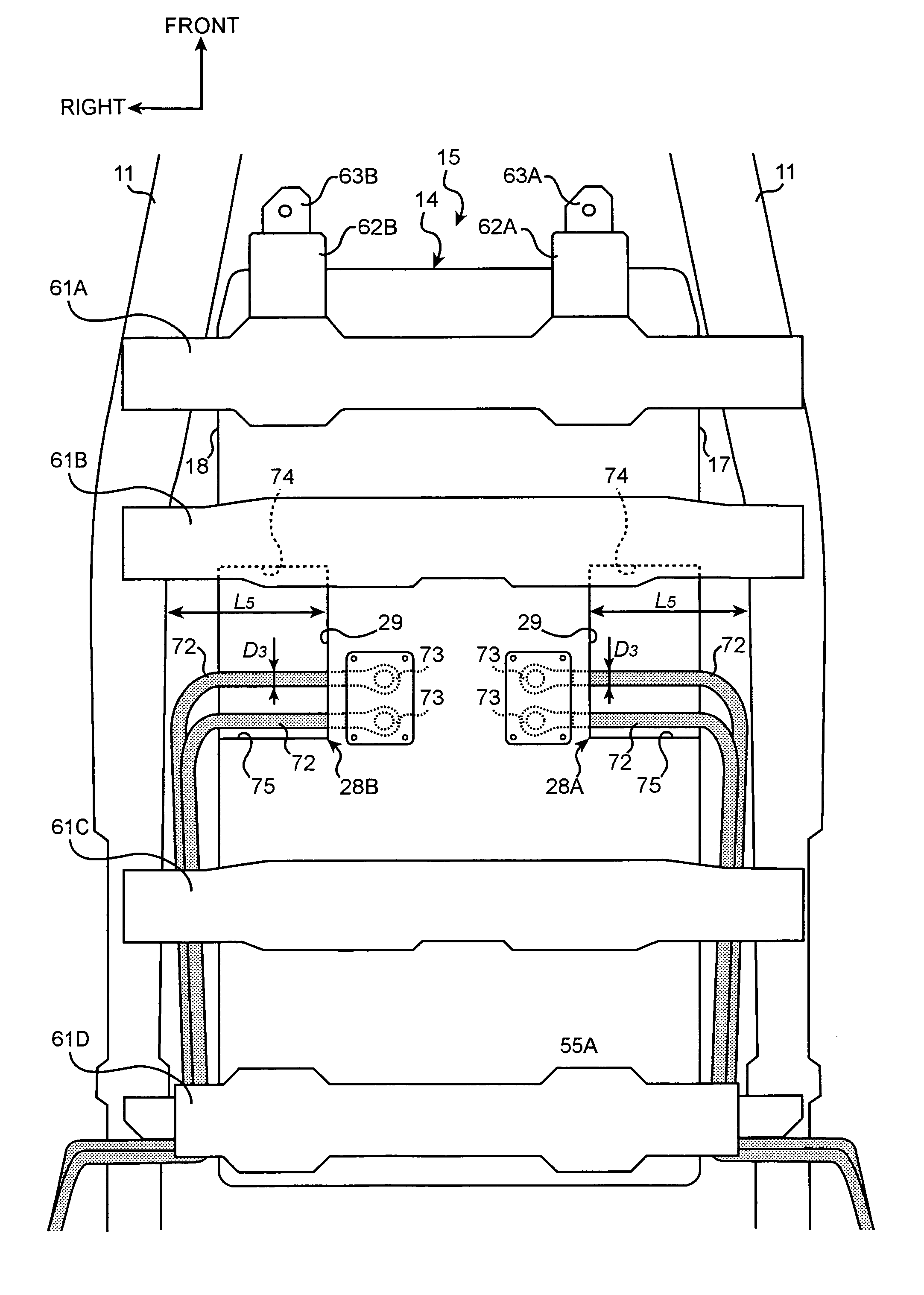
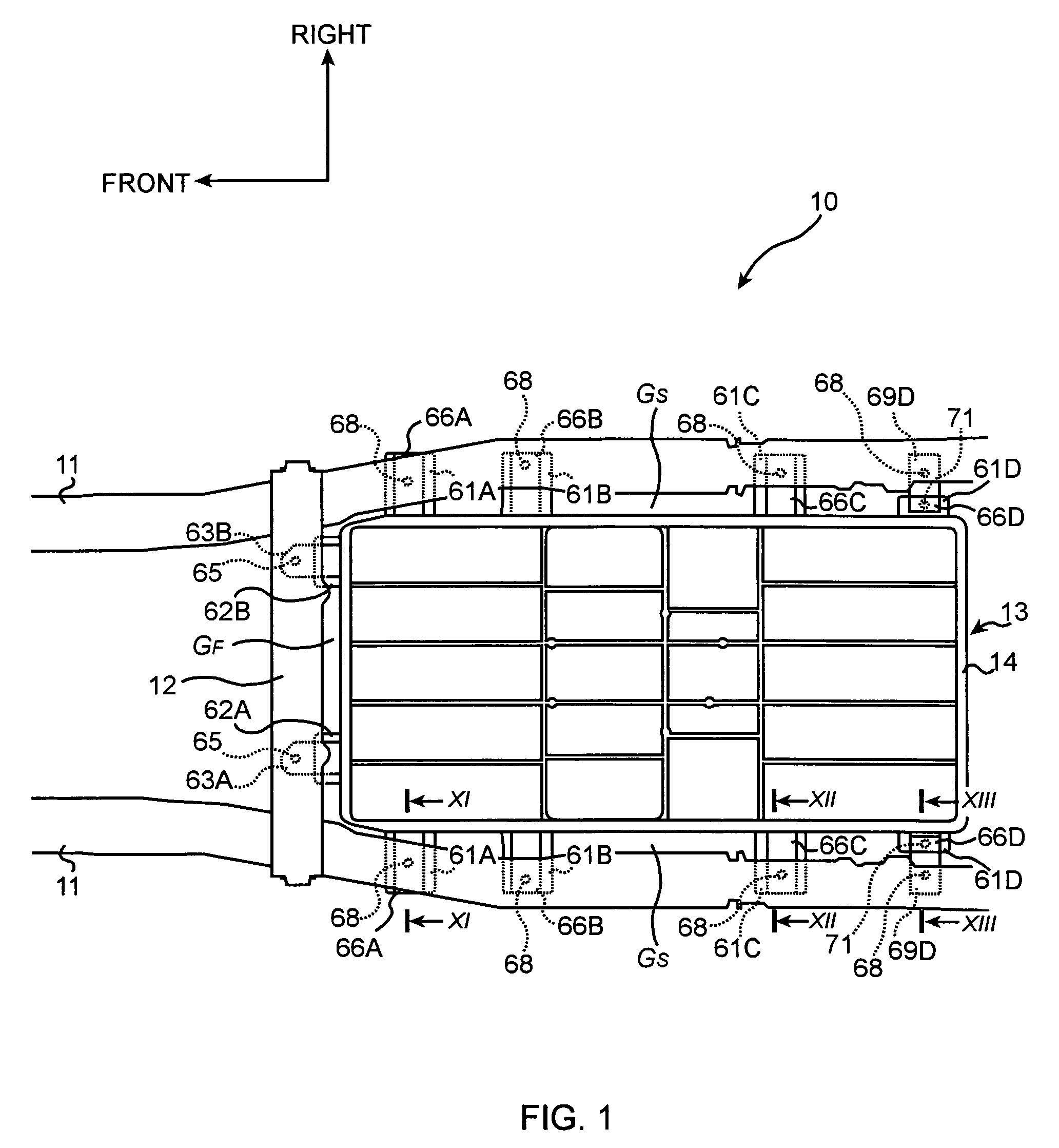
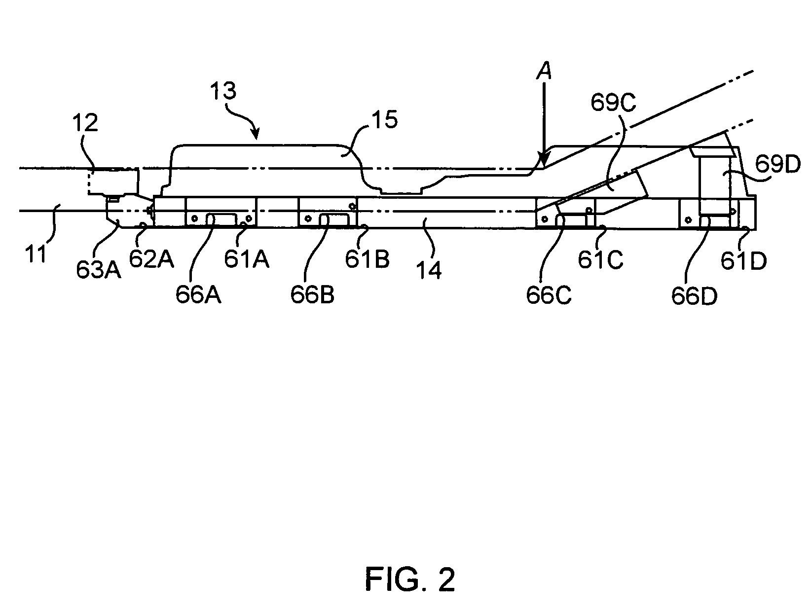
[0037]As shown in FIG. 1, side members (also called ‘body members’ or ‘first body members’) 11 and 11 are mounted on the left and right sides of an electric vehicle 10. The side members 11 and 11 extend in the longitudinal direction of the electric vehicle 10.

[0038]Further, a battery cross member (also called ‘body member’ or ‘second body member’) 12, which extends in the transversal direction (left-right direction) and which connects the pair of side members 11 and 11, is also mounted in the electric vehicle 10.

[0039]The side members 11 and 11 and the battery cross member 12 are iron, and constitute a body of the electric vehicle 10.

[0040]At a position between the pair of side members 11 and 11 and rear of the battery cross member 12, a battery case 13 is disposed. The battery case 13, which is made from polybutylene resin including glass fibers, contains and holds batter...


PUM

PropertyMeasurementUnit
voltageaaaaaaaaaa
voltageaaaaaaaaaa
voltageaaaaaaaaaa

Abstract

A structure for mounting a battery onto an electric vehicle comprises: a high-voltage cable, which is disposed between at least one of first body members of the vehicle and a battery case containing a battery, connecting the battery and an external device disposed outside of the battery case; and a dent portion being formed on a side surface of the battery case faces to the first body member. The dent portion includes a concave side wall, which faces the first body member, having a cable hole portion through which the high-voltage cable is installed. The concave side wall is kept at a distance from the first body member defined based on a diameter of the high-voltage cable.

Description

BACKGROUND OF THE INVENTION[0001](1) Field of the Invention[0002]The present invention relates to a structure for mounting a battery onto an electric vehicle.[0003](2) Description of Related Art[0004]Techniques for connecting cables to batteries contained in a battery case have been known in the art. The following related document 1 discloses an example of such a technique.[0005]As shown in FIGS. 1 and 2 of the related document 1, a battery box (9) is disposed behind a motor (5) and is connected to the motor (5) by cables traveling through the front end of battery box (9).[0006][Related Document 1] Japanese Patent Publication 3819605[0007]However, in some situations, it is impossible to adopt the technique disclosed in the related document 1 of installing the cables through the front end of the battery box (9).[0008]For example, in an electric vehicle (V) shown in the related document 1, it is difficult to connect the cables to the battery box (9) if the cables are disposed between ...

Claims


Application Information

Patent Timeline
Patent Type & Authority Patents(United States)
IPC IPC(8): H01M2/10B60L50/64
CPCB60K1/04B60L11/1877H01M2/1083H01M2/1077Y02T10/705Y02T10/7005B60L50/66B60L50/64Y02T10/70Y02E60/10H01M50/249H01M50/202
Inventor NISHINO, HARUCHIKA
Owner MITSUBISHI MOTORS CORP
Why Eureka
Try Eureka