Switching device

a technology of switching device and contact, which is applied in the direction of electric switches, basic electric elements, electric apparatus, etc., can solve problems such as electrical conduction failure between contacts, and achieve the effect of enhancing the switching performan

Inactive Publication Date: 2010-07-06
KK TOKAI RIKA DENKI SEISAKUSHO +1
View PDF15 Cites 5 Cited by
  • Summary
  • Abstract
  • Description
  • Claims
  • Application Information

AI Technical Summary

Benefits of technology

[0006]According to the above means, the magnetic attractive force of the magnet exerted on the movable contact in the sealing case through the yoke is changed as a result of the magnetic shunt element being moved by movement of the movable element located outside the sealing case. As a result, the movable contact can be moved with respect to the stationary contact without entry of the movable element into the sealing case. Therefore, the movable contact and the stationary contact, which are housed in the sealing case, can be brought into or out of contact with each other without involvement of intrusion of, into the sealing case, lubricant oil or inorganic / organic extraneous matters which are located around the sealing case. As a result, the risk of a problem of an electrical conduction failure between contacts, which would otherwise be caused conventionally by intrusive substances, can be obviated.
[0007]A change in the magnetic attractive force of a magnet exerted on the movable contact in the sealing case through the yoke, the change being induced by movement of the magnetic shunt element, can be made more rapid than that achieved when the magnet itself is moved. As a result, the movable contact can be brought into or out of contact with the stationary contact more rapidly, so that switching performance can be enhanced.

Problems solved by technology

The thus-intruded lubricating oil or the extraneous matters adhere to a space between the movable contact and the stationary contact, which may especially raise a problem of an electrical conduction failure between the contacts being induced by a silicone component.

Method used


Image

  • Switching device
  • Switching device
  • Switching device

Examples


first embodiment

[0015]The present invention is applied to a stop lamp switch for a vehicle, and its first embodiment (a first mode of practice of the invention) will be described hereunder by reference to FIGS. 1 through 3.

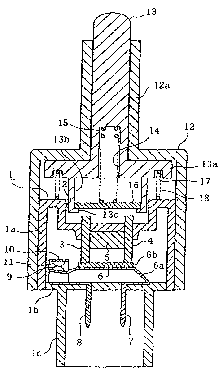
[0016]First, FIG. 1 shows the configuration of an over all vehicle stop lamp switch, and the stop lamp is primarily made up of a sealing case 1. The sealing case 1 includes a case main section 1a and a case bottom plate 1b. The case main section 1a wholly assumes the shape of a square box, wherein an upper surface portion of the main section is closed and wherein a bottom of the main section is opened.

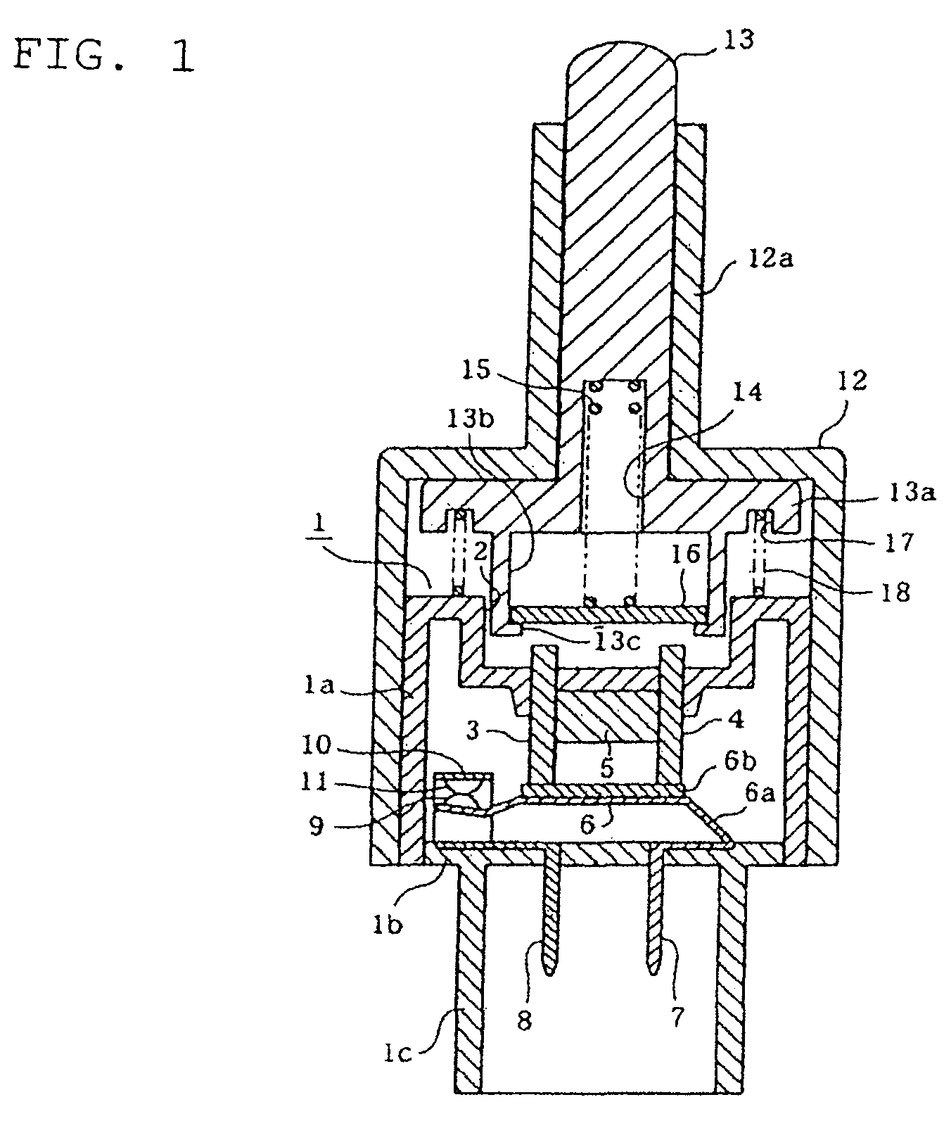
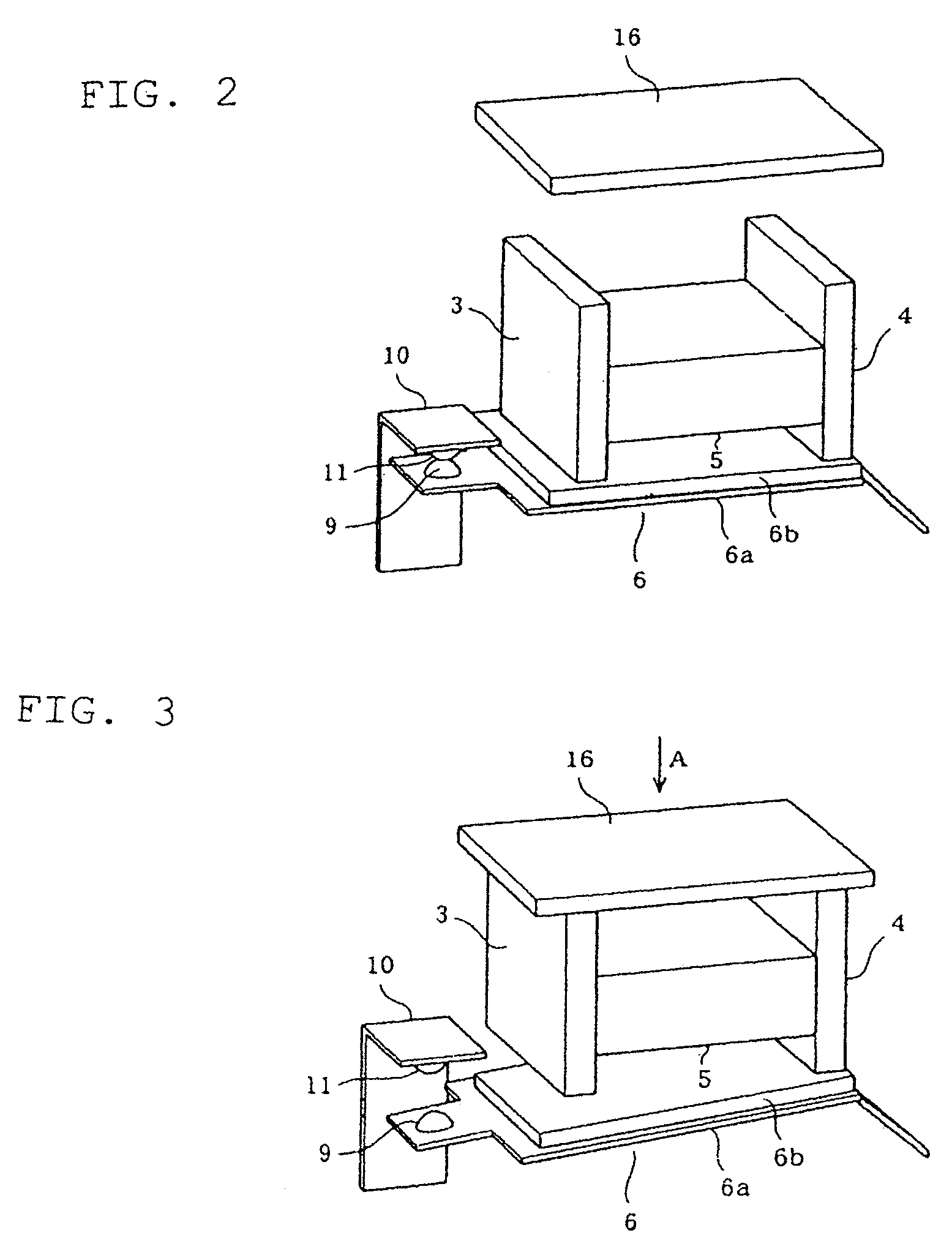
[0017]A recess 2 is formed in the center of the upper surface portion of the case main body section 1a, and yokes 3 and 4 are provided so as to penetrate into the case main body section 1a from the bottom of the recess 2. The yokes 3 and 4 are formed from a magnetic material, such as iron; namely, possess a magnetic property. The yokes are provided as inserts at the time of molding ...

second embodiment

[0040]In a second embodiment shown in FIGS. 4 through 6, a sealing case 21 is first made up of an essentially-dome-shaped case main body section 21a and a case bottom plate 21b in place of the sealing case 1 of the first embodiment.

[0041]As in the case with the yokes 3 and 4 in the case main body section 1a of the first embodiment, yokes 22 and 23 are provided in an upper portion of the case main body section 21a so as to protrude upward of the case main body section 1a much greater than the yokes 3 and 4. The yokes 22 and 23 take the place of the yokes 3 and 4 of the first embodiment; are made of a magnetic material, such as iron; and possess magnetism.

[0042]In the case main body section 21a, the magnet 5 is sandwiched between the yokes 22 and 23 in a contacting manner, and a movable contact 24 is disposed at a position immediately below the yokes 22 and 23. The movable contact 24 takes the place of the movable contact 6 of the first embodiment, and is made up of a contact main pla...

third embodiment

[0059]In a third embodiment shown in FIG. 7, sections 41 and 42 adjoining exteriors of the respective yokes 3 and 4 of the case main body section 1a of the first embodiment are formed so as to extend vertically, thereby making a section 43 adjoining interiors of the respective yokes 3 and 4 extend upwardly.

[0060]As opposed to the yokes 3, 4 and the magnetic shunt element 16 that are made of metal, the case main body section 1a is formed from resin molded by inserting the yokes 3 and 4; in particular, a synthetic resin. Since the case main body section 1a is held in close contact with the yokes 3 and 4, the extending sections 41 to 43 of the case main body section 1a are integrated, as members made of a resin, closely with the yokes 3 and 4. Moreover, the resin is a sound proofing material. Consequently, the extending sections 41 to 43 are integrated, as a soundproofing material made of a resin, closely with the yokes 3 and 4.

[0061]Further, upwardly-stretching portions of the extendi...


PUM


Abstract

Magnetic attractive force of a magnet exerted on a movable contact in a sealing case through yokes changes as a result of movement of a magnetic shunt element induced by movement of a movable element located outside the sealing case. As a result, the movable contact can be brought into or out of contact with a stationary contact without involvement of entry of the movable element into the sealing case.

Description

BACKGROUND OF THE INVENTION[0001]The present invention relates to a switching device having an improved operation structure of a contact.[0002]In general, there has hitherto been provided a switching device with a case housing a stationary contact, a movable contact, and a spring for bringing the movable contact into or out of contact with the stationary contact, wherein a rod-shaped movable element is provided so as to penetrate through the case and wherein, as a result of the movable element being movably operated, the movable contact is moved relatively to the stationary contact, to thus come into or out of contact with the stationary contact (see JP-A-2005-235632).[0003]The switching device of the above configuration is used; for example, as a stop lamp switch for a vehicle (a vehicle stop lamp switch), and lubricating oil applied to various mechanical sections and inorganic and organic substances included in products are present around the vehicle stop lamp switch. In contrast,...

Claims


Application Information

Patent Timeline
Patent Type & Authority Patents(United States)
IPC IPC(8): H01H9/00
CPCH01H13/16H01H36/008H01H13/06
Inventor YAMADA, TOMIOKUMAGAI, KATSUHIDEMIYATA, MASAHIKOOTA, YOSHINORIIDE, TATSUMI
Owner KK TOKAI RIKA DENKI SEISAKUSHO
Why Eureka
Try Eureka