Smart inter-technology handover control

a technology of inter-technology handover and control, applied in the direction of electrical equipment, wireless communication, etc., can solve the problems of loosing connectivity, ping-pong effect, more disruption in service, etc., and achieve the effect of improving inter-technology handover control and avoiding spurious handoff triggers

Inactive Publication Date: 2010-07-06
WSOU INVESTMENTS LLC
View PDF9 Cites 17 Cited by
  • Summary
  • Abstract
  • Description
  • Claims
  • Application Information

AI Technical Summary

Benefits of technology

[0013]It is therefore an object of the present invention to improve inter-technology handover control so that spurious handoff triggers can be avoided and the need for handoff can be anticipated with enough margin for the execution of proactive handoff steps.

Problems solved by technology

This has disadvantages such as causing spurious handoff triggers when the user is still within the WLAN footprint but looses connectivity due to short gaps in the coverage as can be seen from FIG. 1.
Such a ping-pong effect is undesirable as it causes unnecessary signaling traffic as well as may cause more disruption in service than what would have been caused due to lack of WLAN signal for a short while.
However, this degrades the (latency) performance of handoff when the user really exits the hotel door, and hence, loses WLAN connectivity for real.
A further problem encountered with the prior art mainly relying on the signal strength criterion is the difficulty in implementing proactive procedures of handoff.
However, the need for handoff has to be anticipated with enough margin for the execution of proactive handoff steps.
It is not possible to do this reliably based on signal strength measurements alone.
On the other hand, if handoff procedures are started too early (when WLAN signal is still strong), it may result in large number of false starts.
This may create unnecessary signaling burden on the network.

Method used


Image

  • Smart inter-technology handover control
  • Smart inter-technology handover control
  • Smart inter-technology handover control

Examples


Embodiment Construction

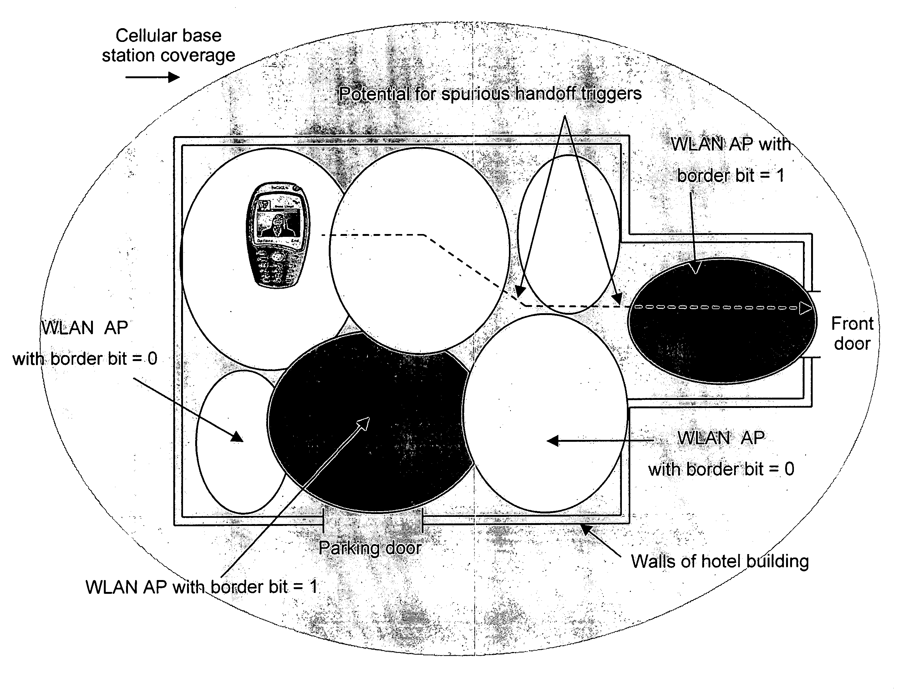
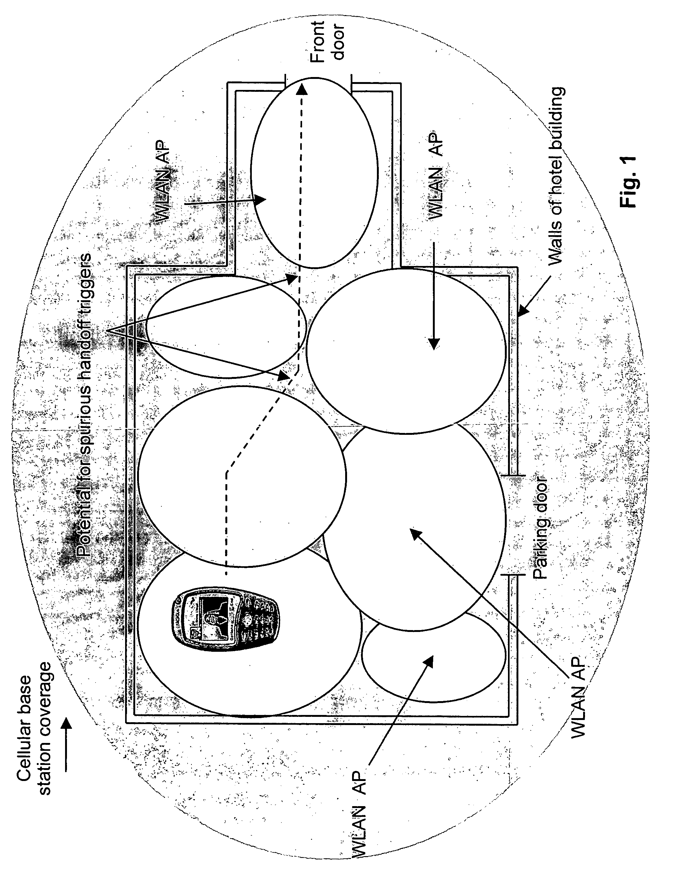
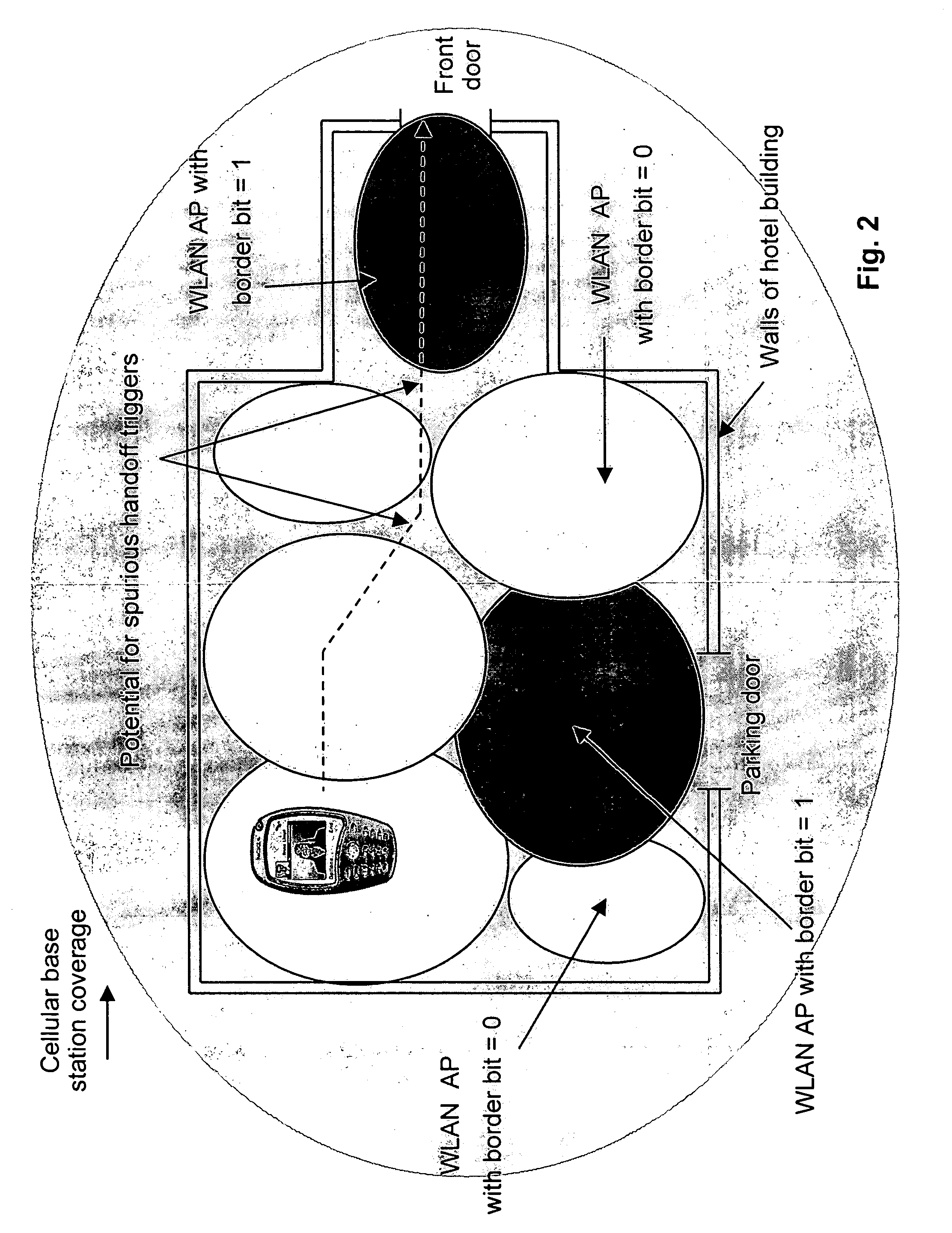
[0036]The idea of the present invention is to control handover between a first technology network and a second technology network by detecting information about regions of an area of the first technology network, and deciding initiating a handover procedure between the first and second technology networks based on the detected region information. The first technology network may be a WLAN and the second technology network may be a cellular network. However, it is to be noted that the present invention is not restricted to any specific radio technology.

[0037]The regions may comprise border regions of an area of the first technology network and non-border regions of this area. Moreover, the handover procedure may be separated in a phase 1 in which handover is prepared and a phase 2 in which handover is carried out. Based on the detected region information, the entire handover procedure can be carried out at once.

[0038]Initiating a handover procedure may include performing an entire ha...


PUM


Abstract

A method and apparatus for controlling handover between a first technology network and a second technology network by detecting information about regions of an area of the first technology network, and deciding whether to initiate a handover procedure between the first and second technology networks based on the detected region information.

Description

[0001]The present application claims the benefit of priority of provisional application Ser. No. 60 / 426,385, filed Nov. 15, 2002, the contents of which are incorporated herein by reference.FIELD OF THE INVENTION[0002]The present invention relates to controlling handover between a first technology network and a second technology network.BACKGROUND OF THE INVENTION[0003]To illustrate a conventional handover between a first and a second technology network the handoff scenario depicted in FIG. 1 is considered. FIG. 1 shows a footprint of a first technology network, e.g. WLAN (Wireless Local Access Network), in a hot spot, which in this case is an indoor environment such as a hotel. The bright circles indicate strong signal footprints of different WLAN access points APs located at the hot spot, while the gray circle indicates a strong signal footprint of an access node of a second technology network, e.g. a cellular base station. As it is shown in FIG. 1, the WLAN geographical coverage a...

Claims


Application Information

Patent Timeline
Patent Type & Authority Patents(United States)
IPC IPC(8): H04W36/00H04W36/14
CPCH04W36/30H04W36/32
Inventor CHASKAR, HEMANT M.TROSSEN, DIRK
Owner WSOU INVESTMENTS LLC
Why Eureka
Try Eureka