
Bearing unit for railway carriages

Inactive Publication Date: 2008-09-02
NTN CORP
View PDF10 Cites 8 Cited by
  • Summary
  • Abstract
  • Description
  • Claims
  • Application Information

AI Technical Summary

Benefits of technology

[0014]The ring members to be butted to the end faces of the inner ring according to the present invention are the rear cover and the oil thrower, or the rear cover and the front cover (substituted for the oil thrower) as shown in FIG. 5, and the ring spacer is provided between the inner race and the rear cover, as well as between the inner race and the oil thrower or the front cover. Since the fretting worn powder is more prone to emerge between the inner race and the rear cover than between the inner race and the oil thrower or the front cover, it is also effective to interpose the ring spacer only between the inner race and the rear cover. Also, since the ring spacer is intended for keeping the inner race and the ring member from directly contacting thus to minimize the emergence of the fretting worn powder, it is preferable to employ a soft metal such as a brass thin plate. To the outer periphery of the ring spacer, an elastic seal such as a rubber ring is integrally fixed thus to assemble a ring spacer with an elastic seal ring as a single component, and such single component is placed between the inner race and the ring member. Disposing the elastic seal ring between the opposing end faces of the inner race and the ring member so as to be elastically pressed thereto achieves a liquid-tight and air-tight seal of the outer periphery of the contact interface between the end faces of the inner race and the ring member, respectively butted to a front and rear faces of the ring spacer. Here, designing the elastic seal ring such that a uniform pressure is applied thereto by the inner race and the ring member allows securing a sufficient margin for the elastic deformation of the elastic seal ring, and preventing hardening and permanent distortion of the elastic seal ring. The worn powder that has emerged and accumulated at the contact interface moves toward the elastic seal ring along the end faces of the ring spacer, but is blocked by the elastic seal ring upon reaching there, to be thereby completely inhibited from intruding into an internal area of the bearing beyond the elastic seal ring.
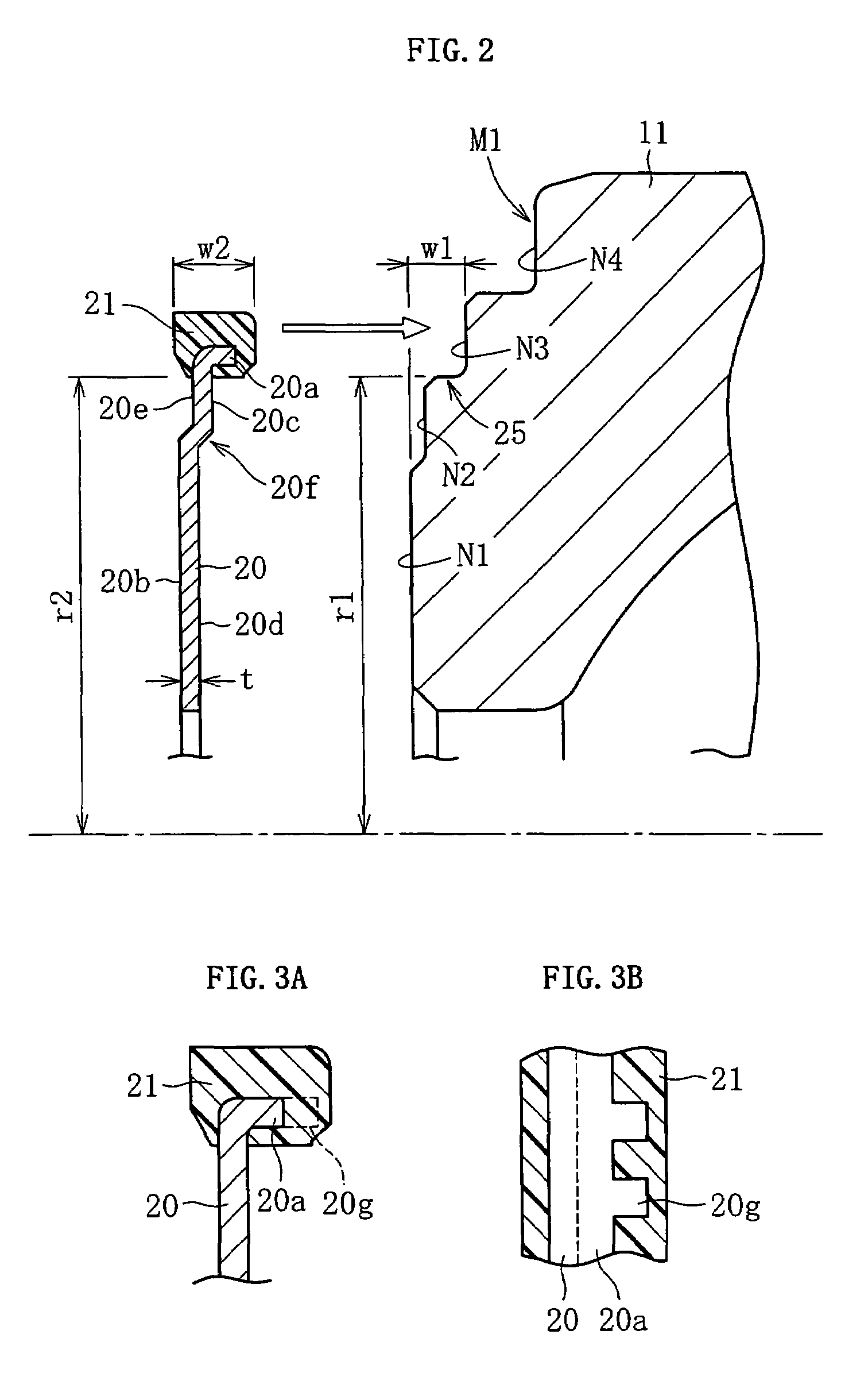
[0028]Further, providing a worn powder storage space inside the elastic seal ring prevents direct adherence of sludge that may be formed from the worn powder and lubricant to the elastic seal ring, thereby preventing premature deterioration of the elastic seal ring because of an internal destruction.

Problems solved by technology

Such deterioration of the elastic seal ring 33a results in emergence of a crack due to degradation in recovery performance, and organic substances deposit in the crack as a sludge to expand the crack, thus to finally destroy the elastic seal ring.

Method used


Image

  • Bearing unit for railway carriages
  • Bearing unit for railway carriages
  • Bearing unit for railway carriages

Examples


Embodiment Construction

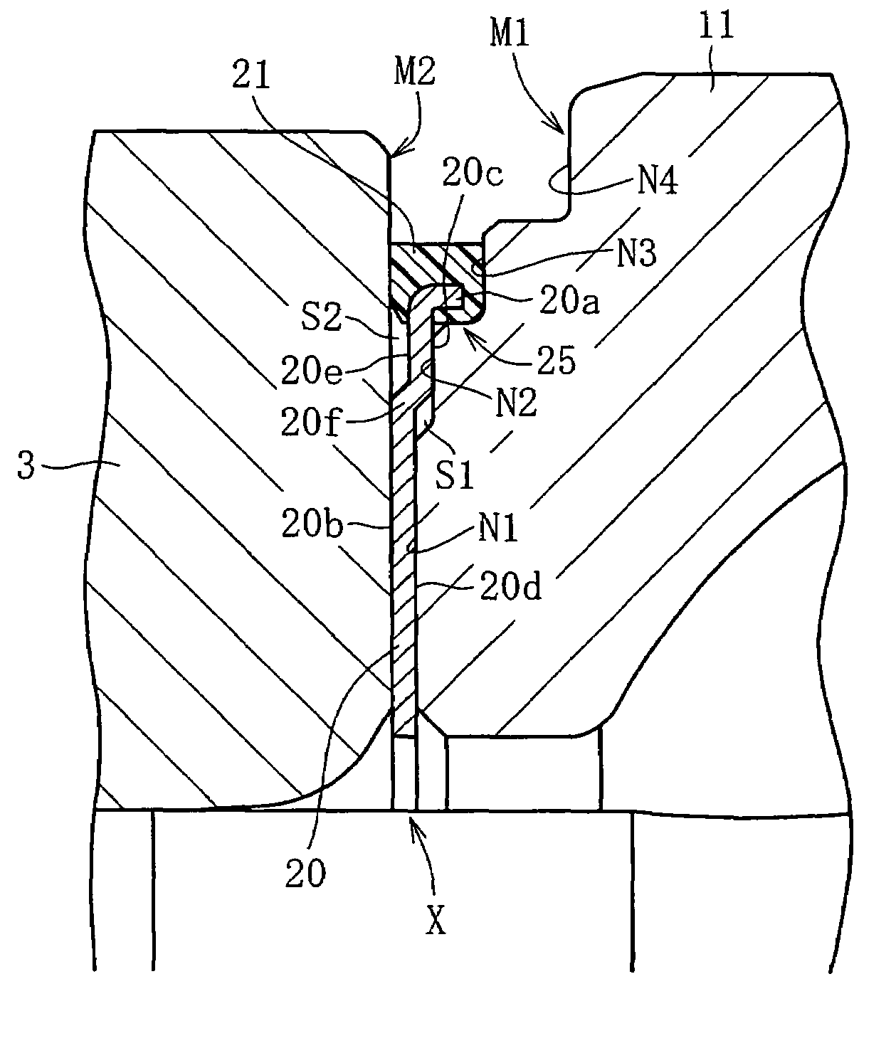
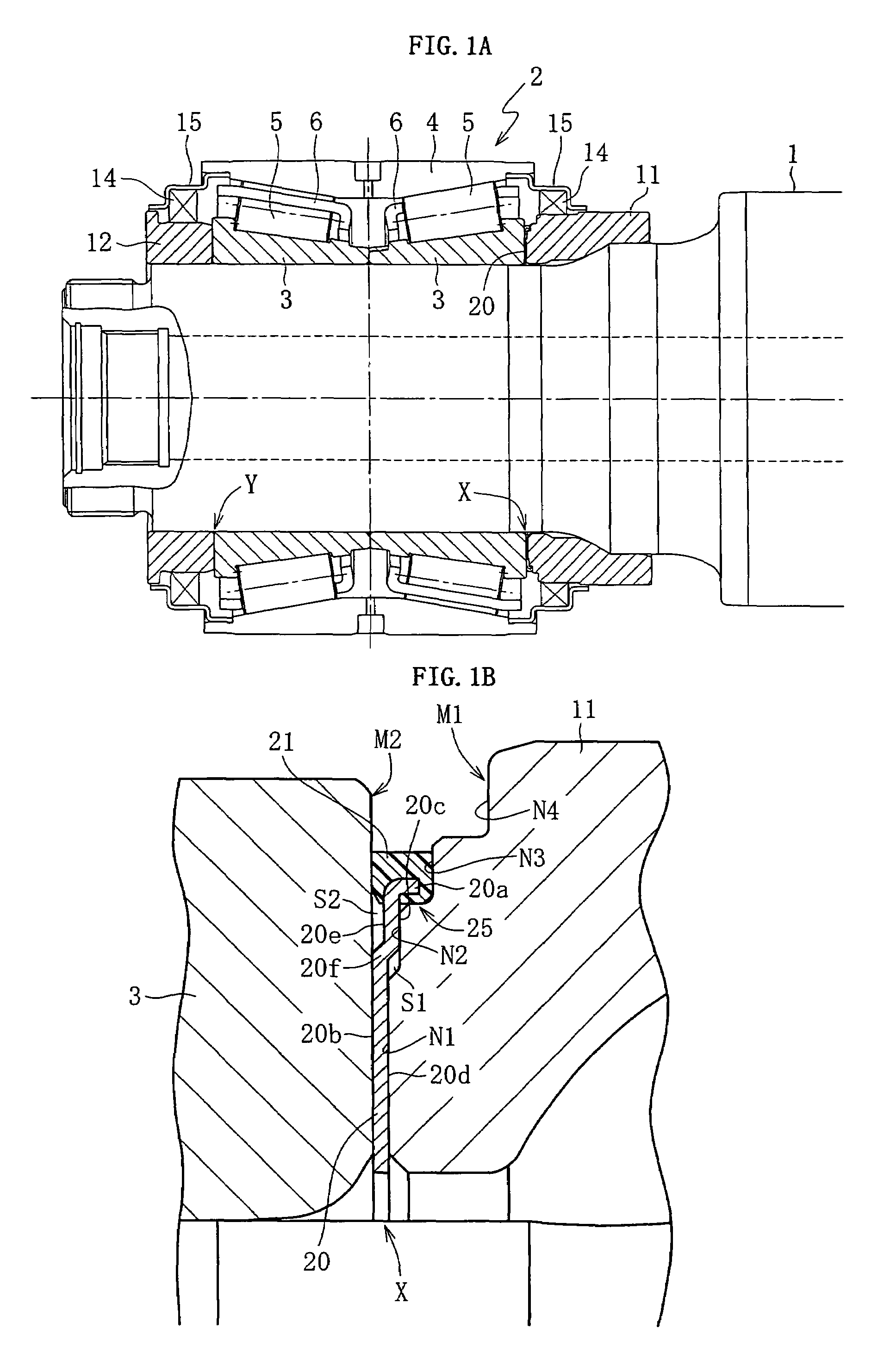
[0040]Referring to FIGS. 1A through 3B, a first embodiment of the present invention will be described hereunder. Since the bearing unit according to this embodiment has a similar basic structure to that of a bearing unit shown in FIG. 5, the same or equivalent constituents are given an identical numeral, and description thereof may be omitted where appropriate.

[0041]According to the first embodiment shown in FIGS. 1A and 1B, a ring spacer 20 with an elastic seal ring is interposed at a contact interface X between an inner race 3 and a rear cover (a ring member) 11, such that the rear end face of the inner race 3 and the front end face of the rear cover 11 is butted to the respective faces of the ring spacer 20. The ring spacer 20 with an elastic seal ring is a unified component built by integrally fixing an elastic seal ring 21 such as a rubber ring, to an outer periphery of the ring spacer 20 constituted of a ring-shaped brass thin plate, for example.

[0042]The ring spacer 20 is for...


PUM


Abstract

Emergence of fretting worn powder is to be suppressed, and intrusion of the worn powder that has emerged into an internal area of the bearing. A ring spacer is interposed between an end face of an inner ring of the bearing to be mounted on a wheel axle, and an end face of a rear cover (ring member) to be mounted on the wheel axle for axial positioning of the inner race with respect to the wheel axle. An elastic seal ring is integrally fixed to an outer periphery of the ring spacer. The elastic seal ring is elastically fitted to an outer circumference of a recessed stepped portion formed on the end face of the rear cover. The elastic seal ring is thus pressed against the opposing end faces of the inner race and the rear cover. Inside the elastic seal ring, a storage space for the worn powder is provided.

Description

BACKGROUND OF THE INVENTION[0001]1. Field of the Invention[0002]The present invention relates to a bearing unit for supporting a wheel axle of a railway carriage via a roller bearing.[0003]2. Description of the Related Art[0004]A bearing unit for a railway carriage wheel axle is generally provided with a roller bearing to be mounted on the wheel axle, and a pair (front and rear) of ring members mounted on the wheel axle for axial positioning of an inner race of the roller bearing. One of the ring members serves as a rear cover butted to rear end face of the inner race, and the other as an oil thrower butted to a front end face thereof, or as a rear cover and a front cover butted to the respective end faces thereof, and both are constituted of a heat-treated carbon steel.[0005]FIG. 5 is a cross-sectional view of an ordinary bearing unit for a railway carriage wheel axle. The bearing unit includes a pair of ring members, namely a rear cover 11 and an oil thrower 12 at the respective e...

Claims


Application Information

Patent Timeline
IPC IPC(8): F16C33/78F16C33/60B61F15/22F16C19/38F16C33/58F16C33/76
CPCB61F15/22F16C19/386F16C33/7813F16C33/768F16C2326/10F16C35/063
Inventor MIKI, DAISUKEISHIKAWA, SHIRO
Owner NTN CORP
Learn More