Fixture and inspection method for an annular seal

a technology of annular seals and fixing methods, applied in the field of annular seals, can solve the problems of increasing the risk of seals that do not conform with design dimensions and tolerances, and the approach can be impractical

Inactive Publication Date: 2010-07-13
GENERAL ELECTRIC CO
View PDF10 Cites 7 Cited by
  • Summary
  • Abstract
  • Description
  • Claims
  • Application Information

AI Technical Summary

Benefits of technology

[0008]From the above, it can be appreciated that an advantage of the present invention is that a relatively uncomplicated, split fixture housing is employed that enables a flexible, multi-segment annular seal, such as a polymeric brush seal of a turbomachine, to be dimensionally inspected relative to one or more critical data while the seal is in a simulated installed condition. Another advantage is that the fixture assembly can be portable, permitting the inspection method to be performed in the field. The fixture assembly and inspection method can be employed to quantitatively and / or qualitatively ensure the concentricity of the inner diameter of the seal and / or compliance with maximum and minimum diametrical dimensions of the seal.
[0009]Other objects and advantages of this invention will be better appreciated from the following detailed description.

Problems solved by technology

As a result, dimensional inspection of the seal in its “free” (uninstalled) state is difficult and leads to an increased risk of seals that do not conform with design dimensions and tolerances.
Though the seal can be inspected after its segments are reassembled during final installation, such an approach can be impractical because of the limited space of typical turbine installations and the difficulty with which such an inspection can be performed in the field.

Method used


Image

  • Fixture and inspection method for an annular seal
  • Fixture and inspection method for an annular seal
  • Fixture and inspection method for an annular seal

Examples


first embodiment

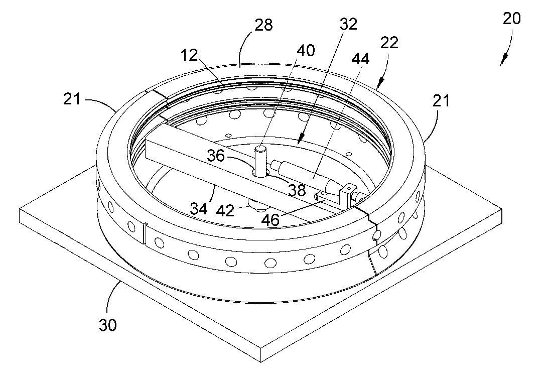
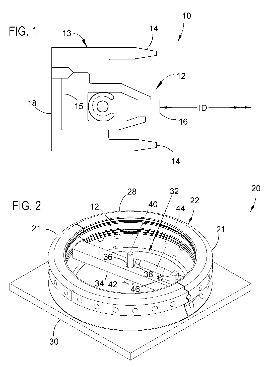
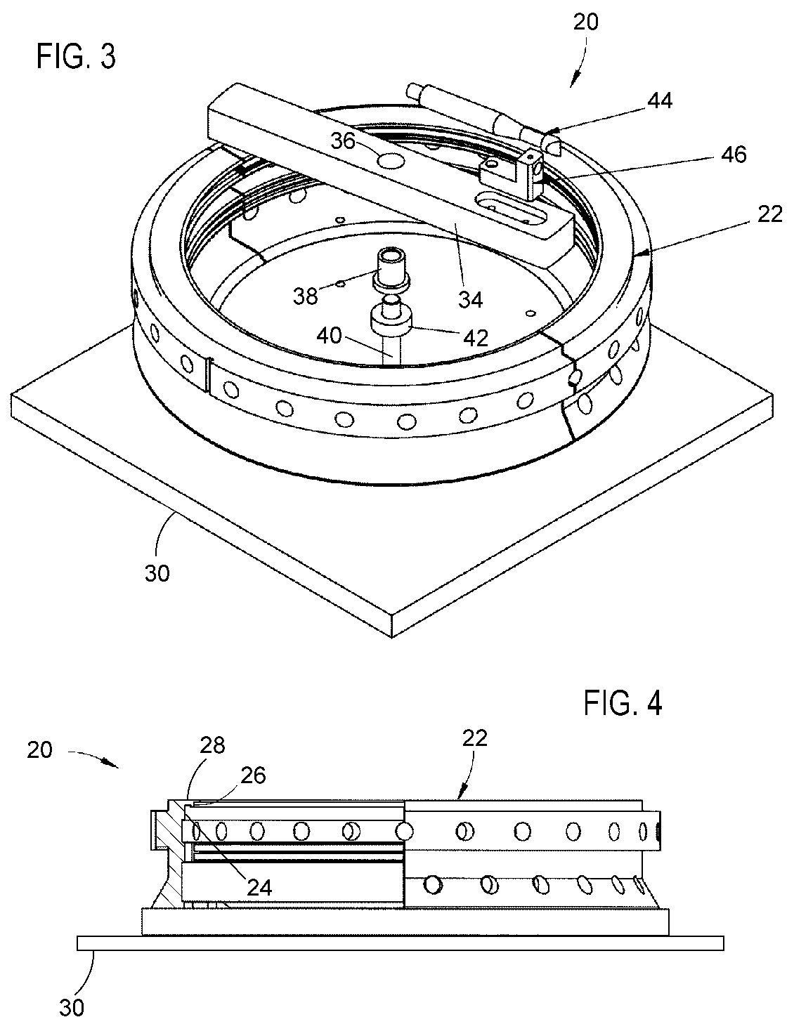
[0021]FIGS. 2 through 4 depict a fixture assembly 20 adapted for assessing the inner diameter and / or concentricity of the brush seal assembly 12 of the seal assembly 10 in accordance with the invention. As represented in FIGS. 2 through 4, the fixture assembly 20 comprises a pair of fixture segments 21 that, when assembled and secured to a base 30, form a fixture housing 22 having an annular shape. The fixture segments 21 and fixture base 30 can be fabricated from a wide variety of materials, and various fastening techniques can be employed to secure the fixture segments 21 to the fixture base 30 so as to provide sufficient strength and rigidity to house the brush seal assembly 12 and support the equipment used to assess the brush seal assembly 12. As evident from FIG. 4, the fixture housing 22 includes a groove 24 located in its interior circumference 26 near an outer rim 28 of the fixture housing 22. The fixture groove 24 is configured and sized to coincide with the diameter, widt...

second embodiment

[0024]FIGS. 5 and 6 depict a fixture assembly 50 adapted for assessing the inner diameter and / or concentricity of the brush seal assembly 12 in accordance with the invention. Similar to the fixture assembly 20 of FIGS. 2 through 4, the fixture assembly 50 is represented as comprising a pair of fixture segments 51 that, when assembled and secured to a base 60, yield a annular fixture housing 52. Also consistent with the previous fixture assembly 20, the fixture housing 52 can be seen in FIG. 6 to have an internal groove 54 located in its interior circumference 56 near an outer rim 58 of the housing 52, and configured and sized to coincide with the diameter, width, and depth of the groove 15 that houses the brush seal assembly 10 within the seal assembly 10 of FIG. 1. Furthermore, the rim 58 of the fixture housing 52 can be shaped and sized to simulate the upper tooth 14 of the seal assembly 10 in FIG. 1. In contrast to the embodiment of FIGS. 2 through 4, the fixture assembly 50 of F...


PUM

PropertyMeasurementUnit
circumferenceaaaaaaaaaa
inner diameteraaaaaaaaaa
internal diameteraaaaaaaaaa

Abstract

A fixture assembly and inspection method by which the internal diameter and / or concentricity of a segmented annular seal can be readily inspected and optionally measured prior to final installation. The fixture assembly has at least two fixture segments supported on a base, by which an annular fixture housing is defined having an outer rim and a groove with a cross-sectional shape corresponding to a cross-sectional shape of the annular seal. The fixture assembly further includes a device or apparatus for assessing at least one dimensional characteristic of the annular seal when installed in the groove of the fixture housing and as the assessing device / apparatus travels along the interior circumference of the fixture housing.

Description

BACKGROUND OF THE INVENTION[0001]The present invention generally relates to annular seals, such as dynamic seals of the type used in turbomachinery. More particularly, this invention relates to a fixture and inspection method by which dimensional characteristics of an annular seal can be ascertained prior to installation.[0002]Labyrinth-type packings and brush seals are widely used in steam turbines and in aircraft and industrial gas turbines to provide dynamic seals between rotating and static turbine components, such as the rotor and diaphragm inner web of a steam turbine. Traditional labyrinth packing comprises a series of teeth that project radially inward from the inner circumference of a static component and toward but out of contact with the adjacent rotary component, thereby defining a series of partial barriers that create a tortuous axial flow path immediately adjacent the surface of the rotary component. Brush seals comprise fibers or bristles that, similar to the teeth o...

Claims


Application Information

Patent Timeline
Patent Type & Authority Patents(United States)
IPC IPC(8): B23Q3/00G01M99/00
CPCF16J15/3296G01B5/12G01B5/252Y10T29/49998Y10T29/49895Y10T29/53978Y10T29/53961Y10T29/49297F16J15/3288
Inventor THERMOS, ANTHONY CONSTANTINECAIRO, RONALD RALPHDEMIROGLU, MEHMETBHATE, NITIN
Owner GENERAL ELECTRIC CO
Why Eureka
Try Eureka