Locking disc spring for pipeline joint

A technology of pipe joints and disc springs, which is applied in the field of locking disc springs, can solve problems such as unclamping, failure of disc spring elastic properties, and joint flying out, so that it is not easy to be disengaged under pressure, well fixed and sealed, and secure The effect of concentricity

Pending Publication Date: 2020-10-30
邱强生
View PDF0 Cites 0 Cited by
  • Summary
  • Abstract
  • Description
  • Claims
  • Application Information

AI Technical Summary

Problems solved by technology

[0002] At present, the quick-fit pipe joints on the market are widely used in the connection of compressed air, inert gas, vacuum, water, oil and other fluid pipelines. The locking structure of the quick-fit joint is clamped with the pipeline. The disc spring in the tight structure will be destructively deformed when the pressure is too large, making it unusable
The supporting surface of the disc spring in the prior art is perpendicular to the direction of the holes, and the elastic performance of the disc spring is prone to failure. When the disc spring is locked, it is easy to eat into the tube and ensure the depth of eating. The force it can bear is limited. At the same time, if the tube is not round or the error is large, it can only be partially eaten into the tube, which will cause problems. The joints fly out during the pressure test

Method used


Image

  • Locking disc spring for pipeline joint
  • Locking disc spring for pipeline joint
  • Locking disc spring for pipeline joint

Examples


Embodiment Construction

[0034] The present invention will be further described in detail below with reference to the embodiments in the accompanying drawings.

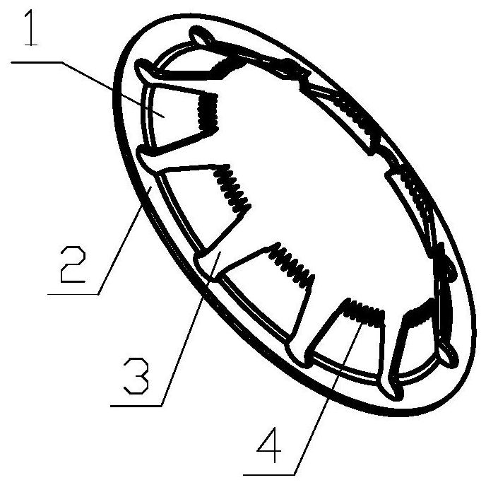
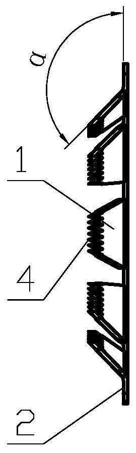
[0035] like figure 1 As shown in / 2, the first embodiment of the locking disc spring for pipe joints of the present invention has a circular positioning edge 2, and the inner side of the positioning edge 2 has a plurality of locking toothed discs extending toward the center Plate 1, the head of each locking toothed disc 1 has sharp teeth 4, a number of locking toothed discs 1 form a conical arrangement, and a disc is formed between two adjacent locking toothed discs 1 The angle α between the slot 3, the positioning edge 2 and the locking toothed disc 1 is 135°.

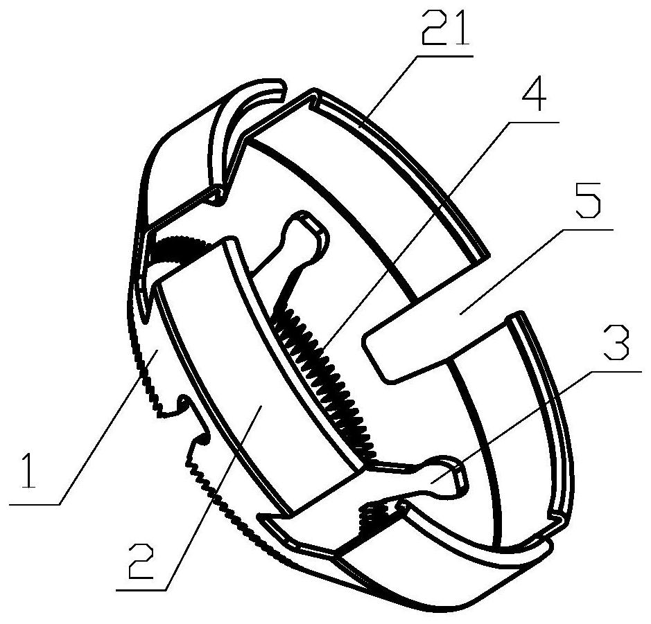
[0036] like image 3 As shown in / 4, the second embodiment of the locking disc spring for pipe joints according to the present invention, the disc spring has a cylindrical annular positioning edge 2, and the inner side of the positioning edge 2 has a plurality of locking toothed di...


PUM


Abstract

The invention discloses a locking disc spring for a pipeline joint. The disc spring is provided with an annular locating edge, wherein a plurality of locking toothed discs extending toward the centerare arranged on the inner side of the locating edge; sharp teeth are arranged on the head parts of the locking toothed discs; the locking toothed discs form conical arrangement; and alternate disc grooves are formed between the locking toothed discs. The locking disc spring for the pipeline joint provided by the invention is better in elasticity, higher in fatigue resistance, and not easy to loseefficacy; the locating edge clings to the inner wall of a main body, so that the concentricity of the toothed disc spring and a pipe is ensured; and the sharp teeth on the sleeve type toothed disc spring are deepened into the pipe after the pipe is inserted into the joint, so that the pipeline is not easy to separate under stress and is safer to use since the disc spring can be deepened into the pipe compared with the prior art that no sharp teeth exist.

Description

technical field [0001] The invention relates to a pipe quick fitting, in particular to a locking disc spring for a pipe joint. Background technique [0002] At present, the quick-release pipe joints on the market are widely used in the connection of compressed air, inert gas, vacuum, water, oil and other fluid pipelines. The locking structure of the quick-release joint is clamped to the pipeline. The disc springs in the tight structure deform destructively when the pressure is too high, rendering them unusable. The supporting surface of the disc spring in the prior art is perpendicular to the direction of the hole position, and the elastic performance of the disc spring is easy to fail, and the disc spring cannot be restored after repeated disassembly and assembly. When locking, the disc spring can be easily eaten into the tube and the depth of the intake is guaranteed. The force that can be tolerated is limited. At the same time, when the tube is not round or the error is ...

Claims


Application Information

Patent Timeline
Patent Type & Authority Applications(China)
IPC IPC(8): F16L37/091
CPCF16L37/091
Inventor 邱强生林根发
Owner 邱强生
Why Eureka
Try Eureka