Brushless DC motor having structures for mounting a hall element and a magnetic ring outside a motor casing

a dc motor and hall element technology, applied in the direction of dynamo-electric components, supports/encloses/casings, instruments, etc., can solve the problems of large volume, large amount of copper and iron, and high cost, and achieve low noise, ensure sensing accuracy and stability, and cost-effective

Active Publication Date: 2014-08-12
ZHONGSHAN BROAD OCEAN
View PDF6 Cites 0 Cited by
  • Summary
  • Abstract
  • Description
  • Claims
  • Application Information

AI Technical Summary

Benefits of technology

[0007]In view of the above-described problems, it is one objective of the invention to provide a brushless DC motor with an external magnetic ring and Hall element that is reasonably structured, compact, cost-effective, installation friendly, and highly reliable.
[0024]1) One end of the motor casing is arranged with an end cover, the center of the outer end surface of the end cover is arranged with a groove with a magnetic ring arranged inside; a Hall induction device, close to the inductive magnetic ring, is also arranged outside the groove. Consequently it is reasonably structured, installation friendly, reliable, and cost-effective. Since the interference is low when magnetic field signals of the inductive magnetic ring of the Hall element changes, it ensures sensing accuracy and stability with low noise and effective control;
[0025]2) Since the Hall element is installed on the circuit board and arranged inside the positioning hole of and a number of strip-shaped holes are arc-shaped and concyclic, it ensures installation concentricity of the Hall elements, which is installation and commissioning friendly with high sensing precision;
[0026]3) The magnetic ring is mounted on the shaft extension end of the rotating shaft through the circular magnetic ring bracket, the magnetic ring is mounted on outer side of the magnetic ring bracket; a hollow shaft seat engaging with the rotating shaft is arranged in the middle of the magnetic ring bracket; outer end of the hollow shaft seat is sheathed with an axial connecting seat and outer end of the axial connecting seat is arranged with a locknut, which locks the shaft extension end of the connecting rotating shaft and tighten the axial connecting seat, thus the structure is compact and stable;
[0027]4) A rotor iron core is composed of an outer ring body, an inner ring body and several ribs connecting the outer ring body and the inner ring body, the outer side of the outer ring body is mounted with a magnetic tile, which is characterized in that it has a reasonable structure and saves materials and costs; and
[0028]5) The outer side wall of the magnetic ring bracket is arranged with a positioning groove, the inner wall of the magnetic ring is arranged with a positioning convex portion engaging the positioning groove so as to enable the magnetic ring to be mounted on outer side wall of the magnetic ring bracket; a retaining ring is arranged at the end of the magnetic ring bracket and the bottom of the positioning groove to block the bottom of the positioning convex portion; the end surface of the magnetic ring bracket is arranged with a buckle clamping the groove arranged on end surface of the magnetic ring so as to enable the magnetic ring bracket to axially hold the magnetic ring. The magnetic ring and the magnetic ring bracket can be simply and firmly installed with accurate positioning.

Problems solved by technology

Disadvantages of above materials are as follows: 1) when weak magnetic ferrite or bonded rubidium iron boron are used in a rotor iron core, the motors, often having a Hall element and a magnetic ring inside, will have a large volume and consume large amounts of copper and iron.
The cost will be relatively high; 2) when sintered rubidium iron boron made of strong magnetic materials are used for a rotor iron core, the magnetism will be extremely strong; if a Hall element and a magnetic ring are arranged inside a motor casing, the Hall element will suffer from great interference when sensing signals.
Thus, the measurement accuracy will be affected leading to inaccurate or even unsuccessful control.
To solve above problems, some motor manufacturers arrange the Hall element and the magnetic ring outside the motor end cover, but following problems still exist: mounting structure layout of the Hall element and the magnetic ring is not reasonable, installation is unfriendly, reliability is poor, and cost is high.

Method used


Image

  • Brushless DC motor having structures for mounting a hall element and a magnetic ring outside a motor casing
  • Brushless DC motor having structures for mounting a hall element and a magnetic ring outside a motor casing
  • Brushless DC motor having structures for mounting a hall element and a magnetic ring outside a motor casing

Examples


Embodiment Construction

[0039]This invention is explained in further detail below with the aid of the example embodiments and attached drawings.

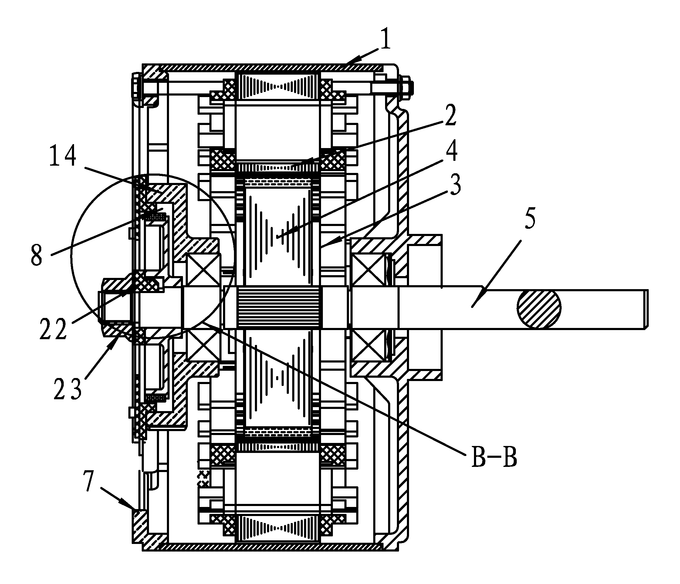
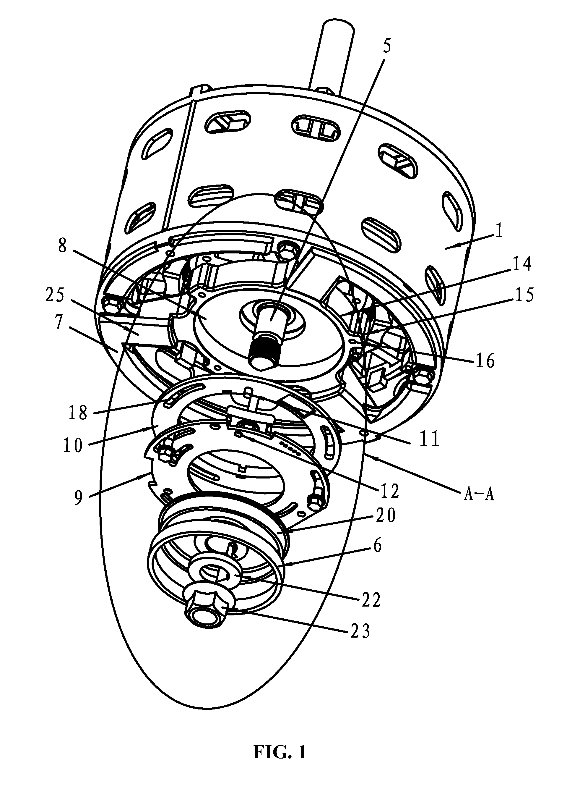
[0040]As shown in FIGS. 1-4, a brushless DC motor comprises a motor casing 1, a stator component 2 and a rotor component 3 respectively arranged inside the motor casing 1. The rotor component 3 comprises a rotor iron core 4 and a rotating shaft 5 supporting the rotor iron core 4 and a shaft extension end of the rotating shaft 5 is arranged with a magnetic ring 6. One end of the motor casing 1 is arranged with an end cover 7, the center of the outer end surface of the end cover 7 is arranged with a groove 8 with the magnetic ring 6 arranged inside. A Hall induction device, close to the inductive magnetic ring 6, is also arranged outside the groove 8.

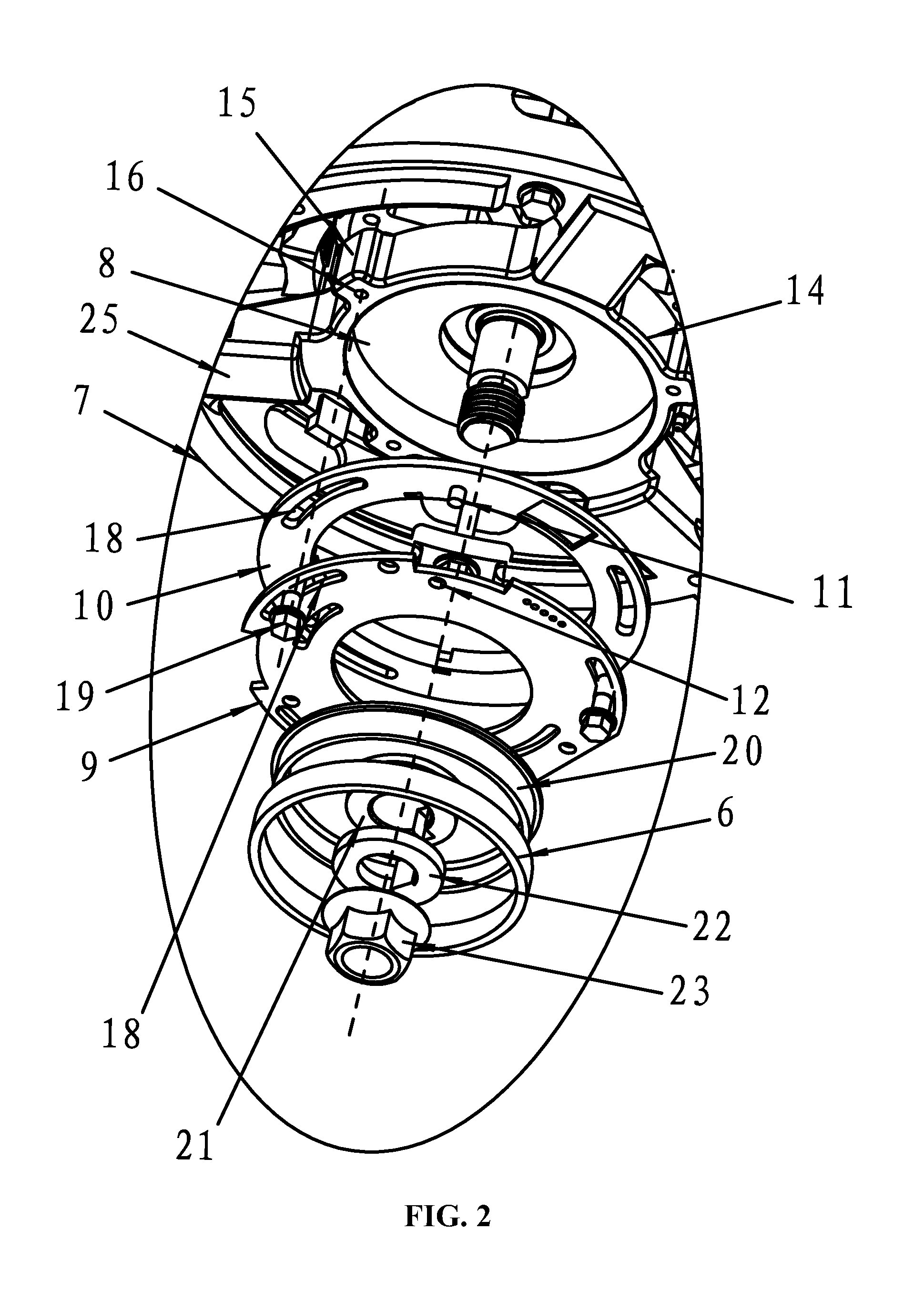
[0041]As shown in FIGS. 1-6, the Hall induction device comprises a circuit board 9 mounted with a Hall element and an installation kit 10, one end of the installation kit 10 is connected with the circuit board 9 and the ...


PUM


Abstract

A brushless DC motor including a motor casing, a stator component, and a rotor component. The stator component and the rotor component are respectively arranged inside the motor casing. The rotor component includes a rotor iron core and a rotating shaft supporting the rotor iron core. A shaft extension end of the rotating shaft is arranged with a magnetic ring. One end of the motor casing is provided with an end cover. The center of the outer end surface of the end cover is provided with a groove. The magnetic ring is arranged inside the groove. A Hall induction device is arranged outside the groove and close to the magnetic ring. The motor is reasonably structured, compact, cost-effective, installation friendly, and highly reliable.

Description

CROSS-REFERENCE TO RELATED APPLICATIONS[0001]This application is a continuation-in-part of U.S. Ser. No. 13 / 283,631 filed on Oct. 28, 2011, now pending, which is based on Chinese Patent Application No. 201020595366.5 filed Oct. 30, 2010. The contents of all of these specifications are incorporated herein by reference.BACKGROUND OF THE INVENTION[0002]1. Field of the Invention[0003]The invention relates to a brushless DC motor.[0004]2. Description of the Related Art[0005]Magnetic materials used in a rotor iron core of a high performance brushless DC motor are divided into two categories: one is weak magnetic ferrite or bonded rubidium iron boron while the other one is sintered rubidium iron boron made of strong magnetic materials. Disadvantages of above materials are as follows: 1) when weak magnetic ferrite or bonded rubidium iron boron are used in a rotor iron core, the motors, often having a Hall element and a magnetic ring inside, will have a large volume and consume large amounts...

Claims


Application Information

Patent Timeline
Patent Type & Authority Patents(United States)
IPC IPC(8): H02K11/00G01B7/30
CPCH02K11/0021H02K5/161H02K29/08H02K11/215
Inventor TANG, SONGFA
Owner ZHONGSHAN BROAD OCEAN
Why Eureka
Try Eureka