Parallel link mechanism and industrial robot

a technology of parallel link mechanism and industrial robot, which is applied in the direction of mechanical control devices, gearing, instruments, etc., can solve the problems of inducing dust release and grease leakage, and affecting the installation effect of the vertical movement shaft mechanism having the bellows, so as to achieve the effect of easy installation

Active Publication Date: 2010-07-13
SEIKO EPSON CORP
View PDF19 Cites 39 Cited by
  • Summary
  • Abstract
  • Description
  • Claims
  • Application Information

AI Technical Summary

Benefits of technology

[0009]Accordingly, it is an objective of the present invention to provide a parallel link mechanism having a transmission mechanism easy to install and an industrial robot.

Problems solved by technology

However, when the bellows extends and contracts, the pressure in the vertical movement shaft mechanism changes, inducing the dust release and the grease leakage.
It is thus difficult for the vertical movement shaft mechanism having the bellows to maintain the increased cleanliness.
This makes it difficult to operate the vertical shaft mechanism having the bellows under the aforementioned particular circumstances.
It is thus necessary to engage the teeth of the spur gears together when assembling the industrial robot, which makes such assembly complicated.

Method used


Image

  • Parallel link mechanism and industrial robot
  • Parallel link mechanism and industrial robot
  • Parallel link mechanism and industrial robot

Examples


Embodiment Construction

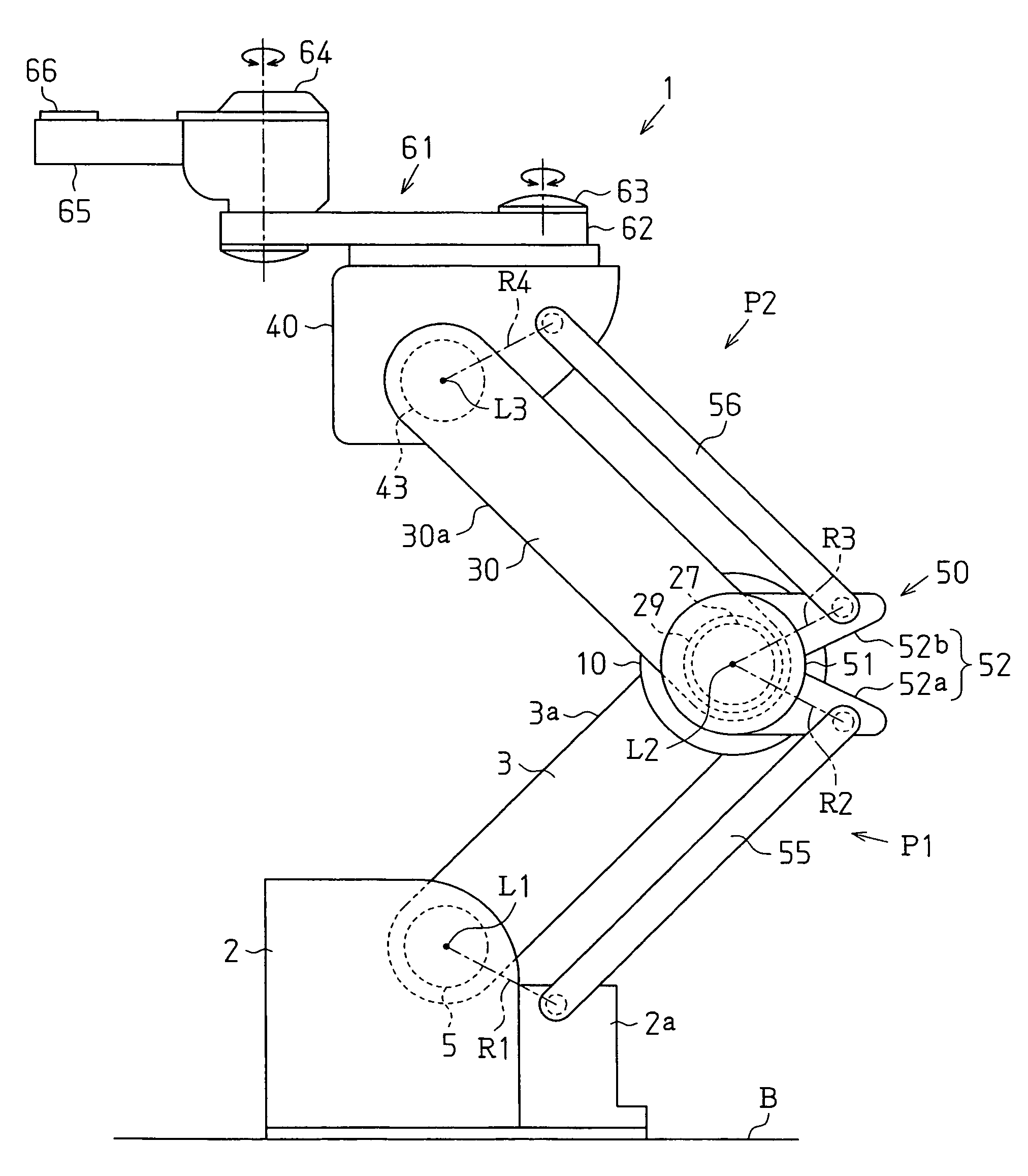
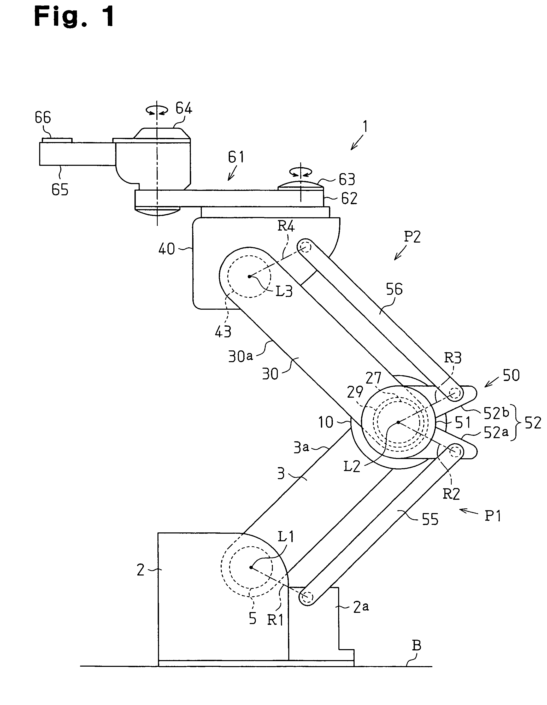
[0021]An embodiment of the present invention will now be described with reference to FIGS. 1 to 4. FIG. 1 is a side view showing an industrial robot 1. FIG. 2 is a cross-sectional view showing the industrial robot 1.

[0022]As shown in FIG. 1, the industrial robot 1 has a substantially parallelepiped fixed base 2 fixed to a floor surface B. Referring to FIG. 2, the fixed base 2 has a cylindrical first connection shaft 5. The first connection shaft 5 is rotatably supported by the fixed base 2 through a bearing 4. The proximal portion of a first arm 3 is connected to the first connection shaft 5. Specifically, a through hole 3H is defined in the proximal portion of the first arm 3 and extends through the first arm 3, allowing communication between the interior and the exterior of the first arm 3. The first connection shaft 5 is secured to the wall of the through hole 3H through securing bolts B1. This permits the first arm 3 to rotate about the axis L1 of the first connection shaft 5. T...


PUM


Abstract

A parallel link mechanism arranged between a fixed base and a movable base includes a harmonic drive gear reducer, a first arm, a second arm, a connection base, a first auxiliary link, and a second auxiliary link. The harmonic drive gear reducer has a body, an input shaft, a first output shaft, and a second output shaft. The first arm has a proximal end pivotally connected to the fixed base and a distal end connected to the body of the reducer. The second arm has a proximal end connected to the second output shaft and a distal end pivotally connected to the movable base. The connection base is arranged outside the second arm with respect to the reducer and connected to the first output shaft. The first auxiliary link is arranged parallel with the first arm and has an end pivotally connected to the fixed base and an end pivotally connected to the connection base. The second auxiliary link is arranged parallel with the second arm and has an end pivotally connected to the connection base and an end pivotally connected to the movable base.

Description

CROSS-REFERENCE TO RELATED APPLICATIONS[0001]This application is based upon and claims the benefit of priority from prior Japanese Patent Application No. 2005-303416, filed on Oct. 18, 2005 and Japanese Patent Application No. 2006-167510, filed on Jun. 16, 2006, the entire contents of which are incorporated herein by reference.BACKGROUND[0002]1. Technical Field[0003]The present invention relates to a parallel link mechanism and an industrial robot.[0004]2. Related Art[0005]General requirements for industrial robots include increased operation speed, improved operation accuracy, and, in certain operation sites, enhanced cleanliness. There are demands that the industrial robots be used under particular circumstance involving use of specific gases or chemicals. One known vertical movement shaft mechanism of a SCARA robot includes a ball screw provided in a vertical movement shaft. The mechanism has a contractible and extensible bellows as a protecting member for preventing release of d...

Claims


Application Information

Patent Timeline
Patent Type & Authority Patents(United States)
IPC IPC(8): B25J9/06B25J17/00
CPCB25J9/042B25J9/046B25J9/1025B25J9/1065F16H21/04B25J18/00F16H49/001Y10T74/20329Y10T74/19Y10T74/20341Y10T74/20305Y10T74/20311Y10T74/20317B25J9/06
Inventor ONO, MASATOSHI
Owner SEIKO EPSON CORP
Why Eureka
Try Eureka