Controlled hay feeder
- Summary
- Abstract
- Description
- Claims
- Application Information
AI Technical Summary
Benefits of technology
Problems solved by technology
Method used
Image
Examples
Embodiment Construction
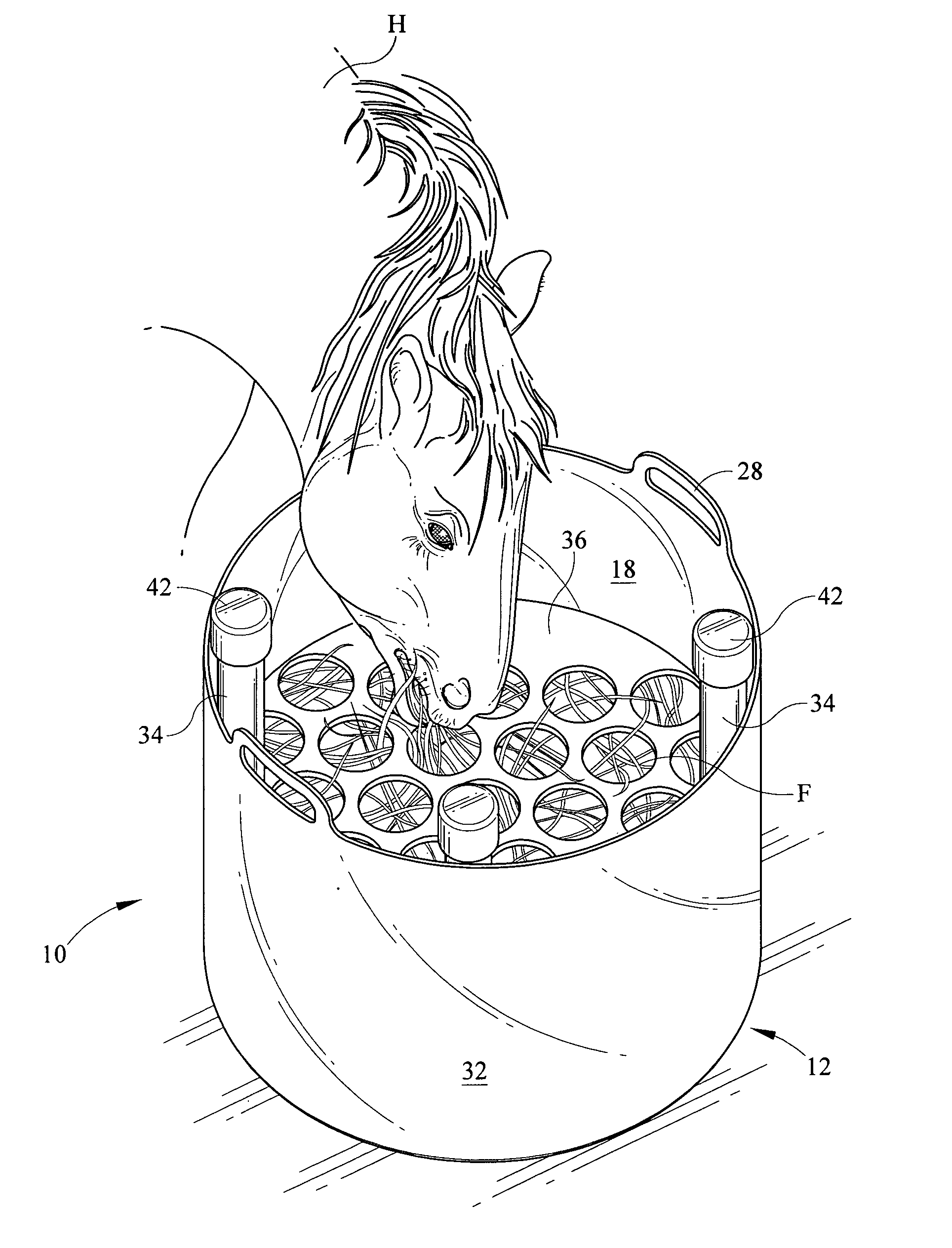
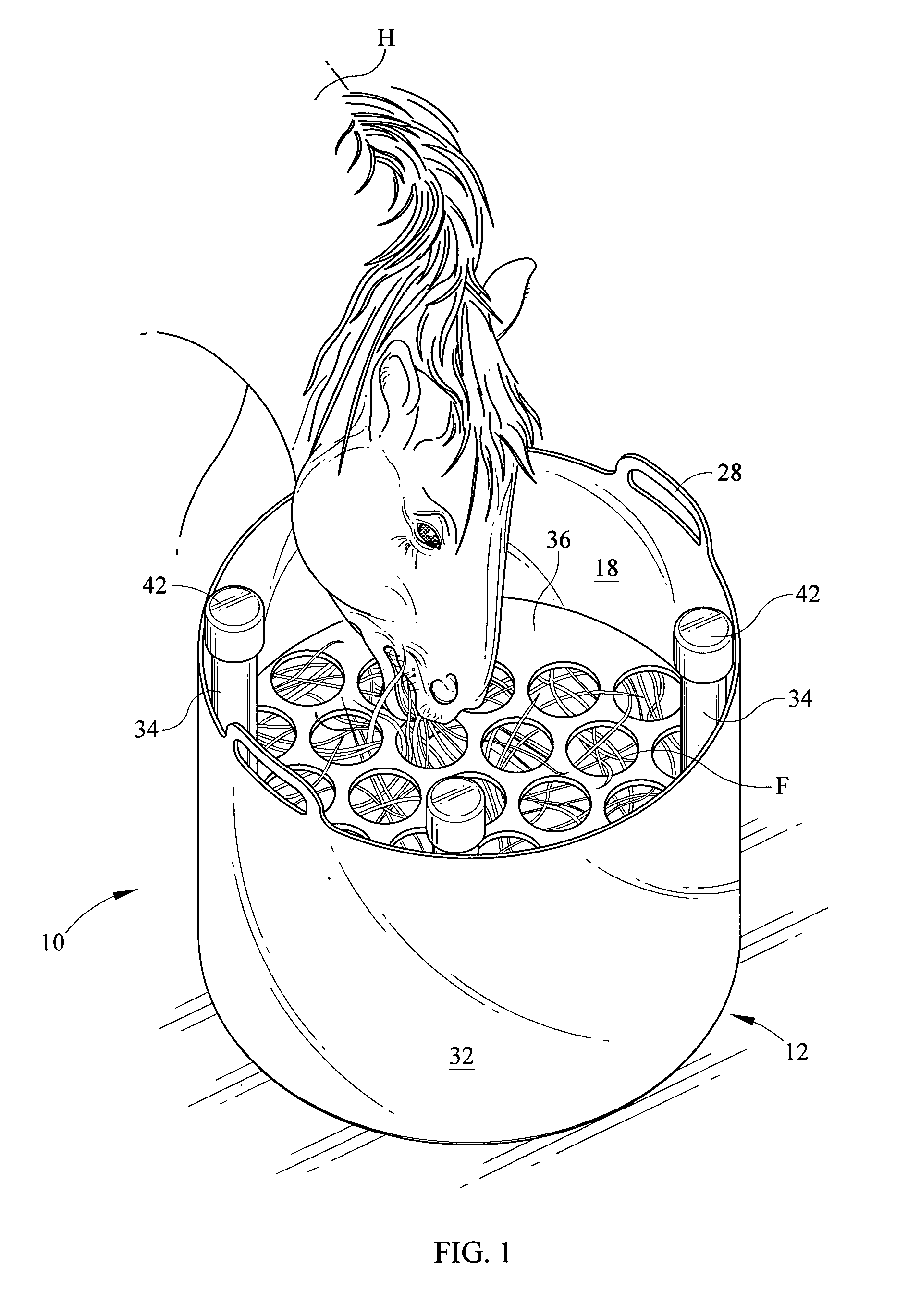
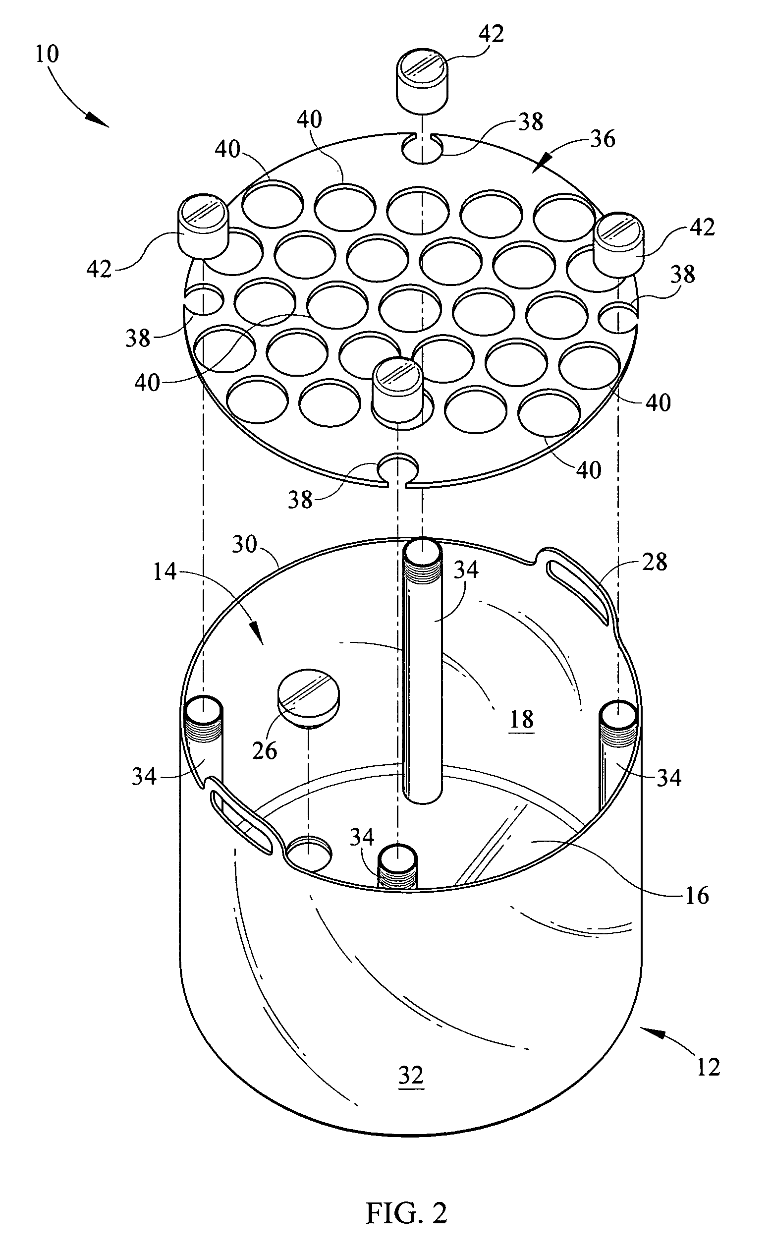
[0016]Referring now to the drawings, it is seen that the controlled hay feeder of the present invention, generally denoted by reference numeral 10, is comprised of receptacle 12 that has an open top 14, a closed bottom 16, and an inner surface 18. As seen in FIG. 4, the bottom 16 may have an additional compartment 20 such that an additional wall 22 is provided to give the bottom a “false bottom.” A plug 24 is removably attached, threadably or otherwise, to the bottom 16, or to this additional wall 22, or to the side of the receptacle (neither illustrated) in order to gain access to the compartment 20. The compartment can be filled with sand S or other appropriate substance in order to help prevent the controlled hay feeder 10 from tipping over during use. Alternately, as seen in FIG. 5, no compartment is present and the bottom 16 is the sole bottom wall of the receptacle 12. A plug 26 is removably attached, threadably or otherwise, in order to allow the receptacle to be drained as n...
PUM
 Abstract
Description
Claims
Application Information
 - R&D
- Intellectual Property
- Life Sciences
- Materials
- Tech Scout
- Unparalleled Data Quality
- Higher Quality Content
- 60% Fewer Hallucinations
Browse by: Latest US Patents, China's latest patents, Technical Efficacy Thesaurus, Application Domain, Technology Topic, Popular Technical Reports.
© 2025 PatSnap. All rights reserved.Legal|Privacy policy|Modern Slavery Act Transparency Statement|Sitemap|About US| Contact US: help@patsnap.com


