
Diversion under load conditions in distribution systems

a distribution system and load technology, applied in the direction of pipe elements, branching pipes, pipe connection arrangements, etc., can solve the problem of difficult placement of pipes, and achieve the effect of efficient and safe intervention

Inactive Publication Date: 2010-07-13
VILLAR COLQUELL D FRANCISCO JAVIER
View PDF8 Cites 4 Cited by
  • Summary
  • Abstract
  • Description
  • Claims
  • Application Information

AI Technical Summary

Benefits of technology

"The present invention provides a new design for a tap used in pipes, which simplifies the work to be done and reduces the size and cost of the tap. The tap uses a single guillotine to make cuts for sectioning the pipe, which can be re-used as many times as necessary. The guillotine is outside the tap, making it more solid and easier to install. The tap can be installed in pipes made of composite, plastic material, or the like, providing a tight enclosure between the parts of the tap body and the contour of the tube. The tap has openings for the passage of the guillotine, which are sealed with conventional techniques. The guillotine is designed to access from the outside openings, cutting by means of its movement perpendicular to the pipeline in the two positions opposing the openings. The separation of the cut pipe portion is carried out with the aid of a collar or flange which is fixed to the pipe portion before forming the tap, and which is made integral with the pipe portion by means of any mechanical operation, by adhesion or by means of heat-sealing. The tap ensures the upstream supply of fluid without needing to place any bypass."

Problems solved by technology

In both versions, the configurations adopted by the tightness lids have the advantage, compared to conventional stoppers, of being contained in a plane perpendicular to the emission of fluid, facilitating their closing, whereas in the case of using a stopper, the latter must always overcome the pressure of the emanated fluid, which makes its placement difficult, this being an especially significant piece of data in medium and high-pressure networks, and forming a potential risk.

Method used


Image

  • Diversion under load conditions in distribution systems
  • Diversion under load conditions in distribution systems
  • Diversion under load conditions in distribution systems

Examples


Embodiment Construction

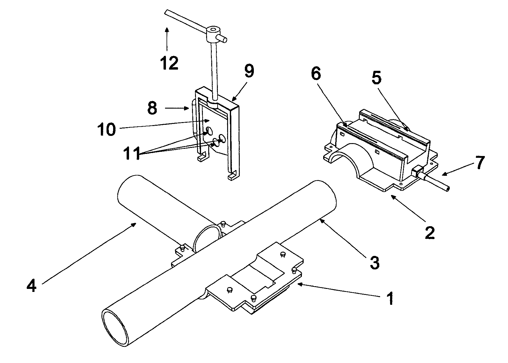
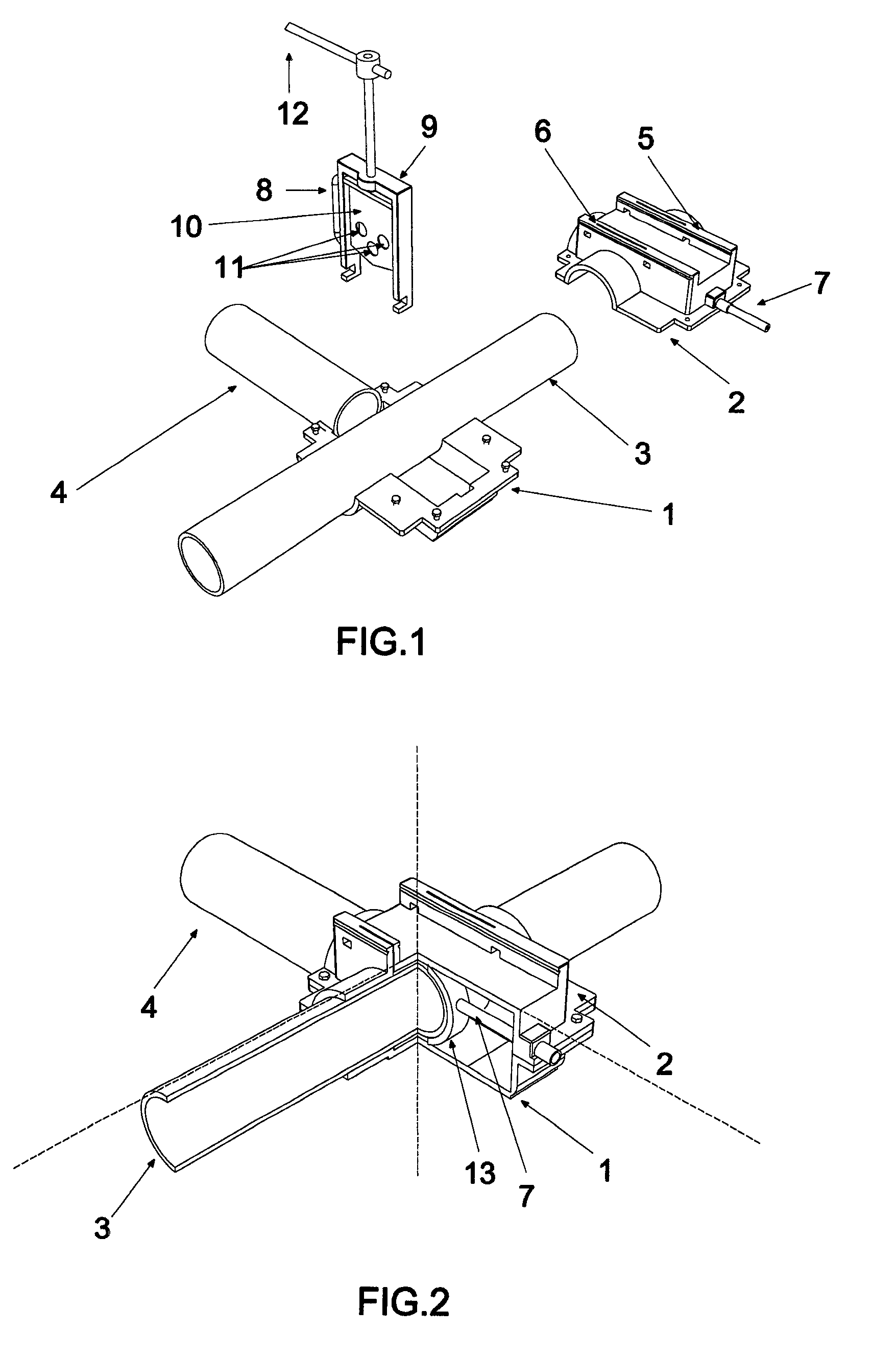
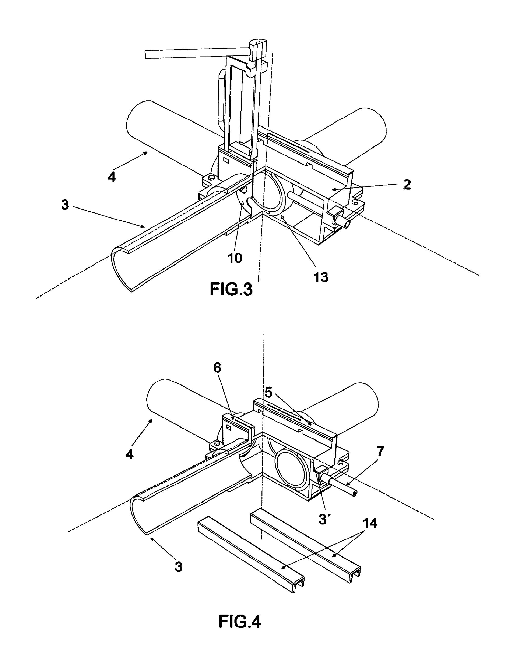
[0022]The preferred embodiments of the hot tap for fluid distribution networks proposed by the invention will be described below, the graphic depictions shown in the attached drawings being considered as the reference basis. At this point, the clarifying comment must be made that, according to that mentioned above, the invention has been designed for its preferred use in conduits formed by polyethylene pipes, but this must not be considered as limiting, because its essence is also applicable to pipes constructed with other types of materials, with the use of techniques for joining by gluing, sealing gasket, or appropriate in each case. When the pipes are made of polyethylene, joining by electrofusion is preferred.

[0023]As can be seen in FIG. 1, the tap comprises two main components 1, 2, configured to be complementarily coupled in the chosen position around a pipe 3 in which a tap is to be carried out, further having an inlet for the incorporation of a second pipe with reference num...


PUM

PropertyMeasurementUnit
sizeaaaaaaaaaa
pressureaaaaaaaaaa
adhesionaaaaaaaaaa

Abstract

The invention relates to a diversion which can be used under load conditions in a fluid distribution system without interrupting the fluid supply or installing a by pass. The diversions consists of a body that is formed by two complementary components including an upper component comprising openings which are oriented transversely to the direction of the pipe to be cut off, which are equipped with seals and which are designed such as to enable the insertion and passage of a cutting blade that is associated with an external guillotine. The aforementioned upper component comprises an inner collar or flange which can be coupled and secured to the pipe segment to be cut off, said collar or flange being joined to a threaded longitudinal element which extends externally and which is used to remove the cut-off pipe segment. The invention also includes elements for sealing the openings once the cutting operations have been performed and the guillotine has been removed.

Description

[0001]This application is a national stage entry of PCT / ES2006 / 070120 filed Jul. 28, 2006, under the International Convention claiming priority over Spanish Application No. P200501885 filed Jul. 29, 2005.FIELD OF THE INVENTION[0002]The invention relates to a tap carried out in fluid distribution networks whereby the supply is assured during the placement operation without needing to place any bypass.OBJECT OF THE INVENTION[0003]The object of the invention consists of obtaining, in an existing fluid transport network, a tap which can inserted without needing to cut off the supply or install a bypass, minimizing the number of fixtures, the weldings and the execution time by means of a simple tap allowing an efficient and safe intervention. The invention is aimed at the industrial pipeline sector.BACKGROUND AND SUMMARY OF THE INVENTION[0004]As a reference to the current state of the art, under-pressure tapping is currently carried out through a drilling tool located inside the fixture ...

Claims


Application Information

Patent Timeline
Patent Type & Authority Patents(United States)
IPC IPC(8): F16L41/04F16L47/34
CPCF16L41/06F16L47/345Y10T137/6123Y10T137/612Y10T137/0469F16L47/34
Inventor VILLAR COLQUELL, D. FRANCISCO JAVIER
Owner VILLAR COLQUELL D FRANCISCO JAVIER
Learn More