Method and apparatus for vacuum collecting and gravity depositing drill cuttings

a vacuum collection and drilling cutting technology, applied in the field of drill cutting collection, to achieve the effect of preventing plugging and overloading, and removing bottlenecks

Inactive Publication Date: 2010-07-13
REDDOCH SR JEFFREY A
View PDF46 Cites 9 Cited by
  • Summary
  • Abstract
  • Description
  • Claims
  • Application Information

AI Technical Summary

Benefits of technology

[0008]Drill cuttings and any residual fluid contaminants still on the drill cuttings as they leave the shale shakers are deposited into a cuttings trough where they are first vacuumed, via a hollow tube positioned in the cuttings trough, into a continuous open end discharge hopper that has one end positioned into a fluid-filled tank or body of water. A vacuum is maintained upon the continuous open-ended discharge hopper by a fluid seal at one end opposite the vacuum pump. As drill cuttings and contaminant drill fluid are vacuumed from the cuttings trough to the continuous open end discharge hopper, the vacuum volume expands and air flow slows down in the discharge hopper. The heavy drill cuttings and contaminant drill fluids drop by gravity into the fluid forming the vacuum seal. Therefore, a continuous feed of drill cuttings and contaminant residual fluid being transferred by vacuum directly into a fluid tank or hopper for further treatment of the cuttings with no mechanical moving parts, other than the vacuum pump. There are no manifolds, or valves and no need to transfer or move cuttings boxes. This eliminates the bottlenecks in the process by preventing plugging and overload due to spikes in production. In some cases where the cuttings are not contaminated they may be deposited directly into the sea.
[0010]Cuttings slurry visibility is now possible via the open top slurry tank made possible by the continuous vacuum hopper which allows the cuttings slurry to be discharged directly into the open cuttings grinding tank. As the cuttings grind, they turn the cuttings into clay, which takes up any free fluid in the tank rapidly. The slurry often thickens and plugs the grinding unit, thus visibility is essential for the operator to dilute the slurry in time to prevent back up of the system causing expensing drilling rig downtime.
[0011]Additional embodiments disclosed herein show how the continuous open-ended discharge vacuum hopper may be used in combination with other cuttings processing equipment, for example the vacuum hopper may be connected to a cuttings dryer system. The vacuum hopper may also be connected fluidly to a cuttings dryer whereby the continuous open-ended discharge vacuum hopper discharges directly into the cuttings dryer, the cuttings dryer is sealed to allow no openings to allow for a loss of vacuum efficiency, and the discharge end of the cuttings dryer is fluidly connected to the sea, allowing the cuttings to be discharged directly into the sea. This completely sealed system eliminates many places that contaminant mud can splash onto the rig or into the sea.

Problems solved by technology

Multiple open-ended discharge hoppers are placed within the grinding tank to allow for vacuuming from different cuttings troughs, heretofore not possible due to hose plugging problems inherent to cuttings vacuum systems.

Method used


Image

  • Method and apparatus for vacuum collecting and gravity depositing drill cuttings
  • Method and apparatus for vacuum collecting and gravity depositing drill cuttings
  • Method and apparatus for vacuum collecting and gravity depositing drill cuttings

Examples


Embodiment Construction

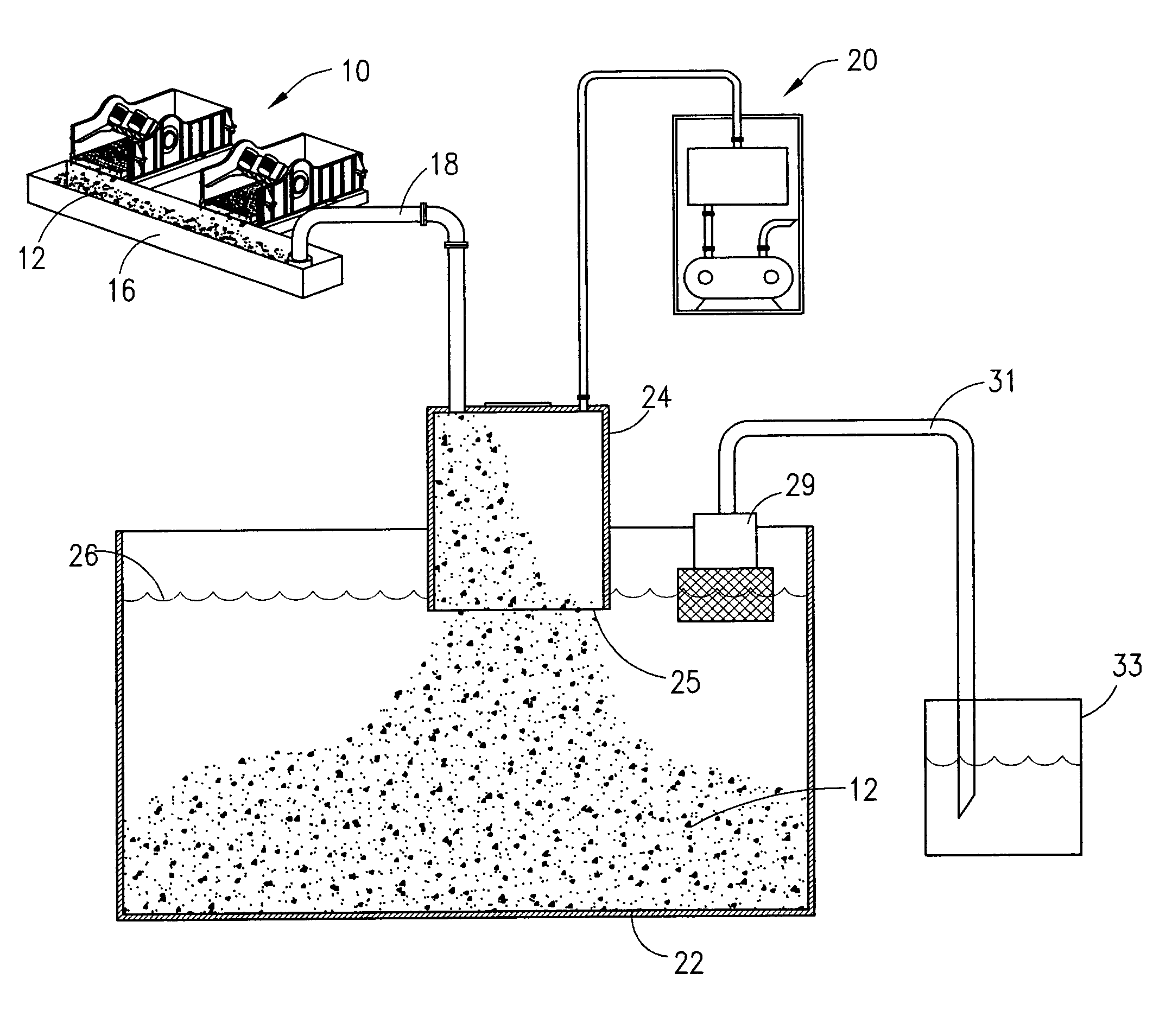
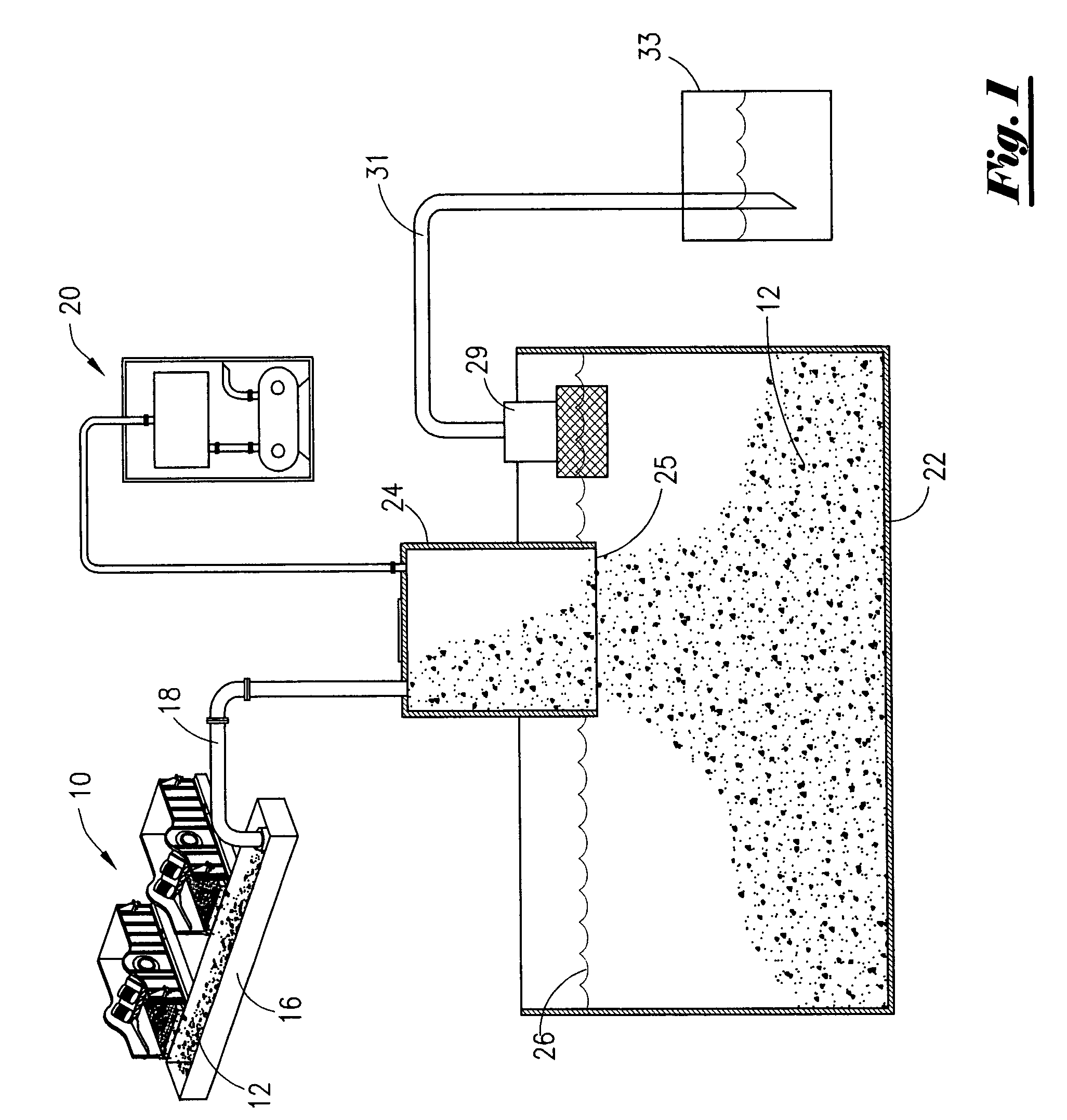
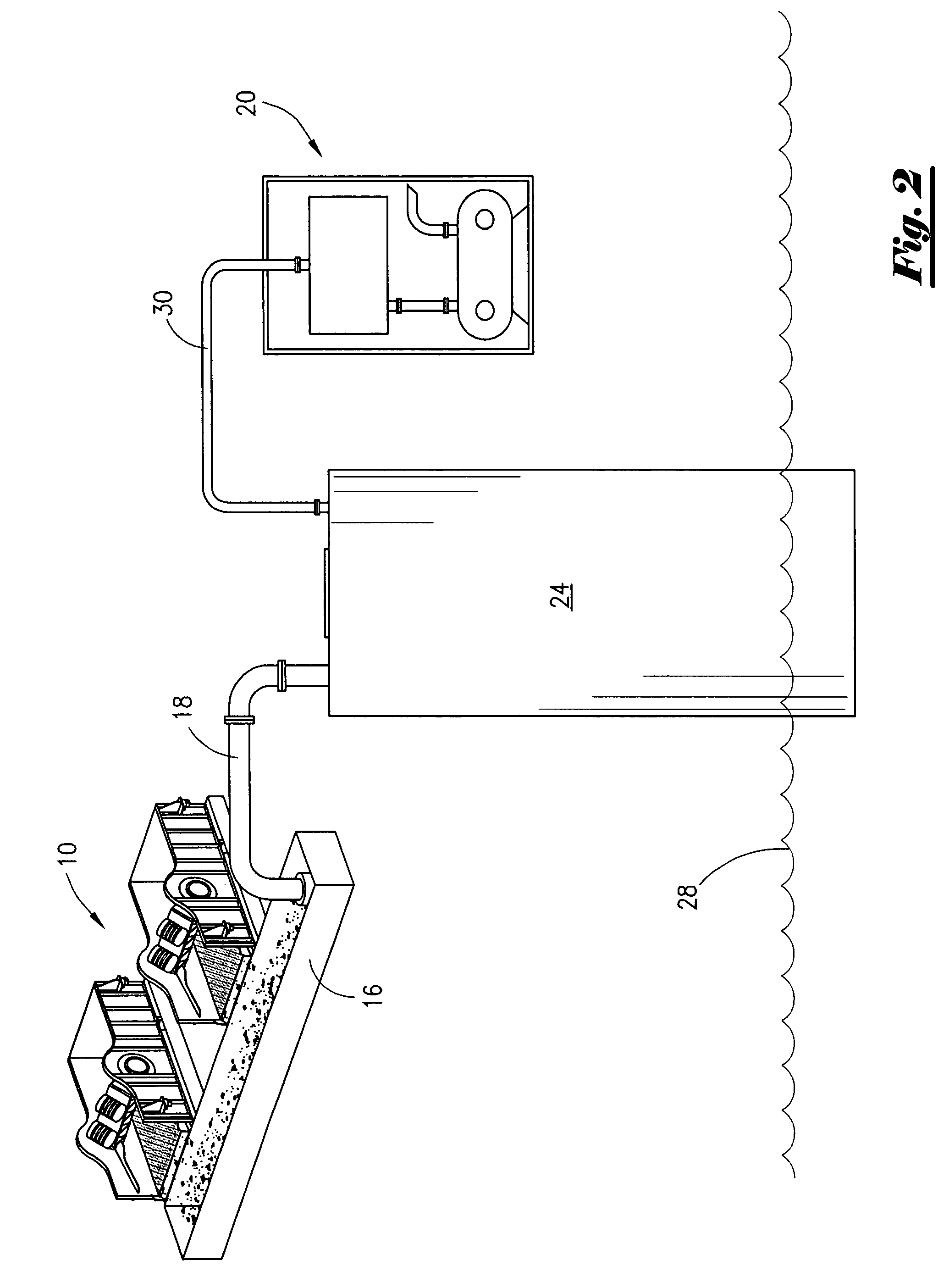
[0025]As seen In FIG. 1, a group of shale shakers 10, typically composed of sets of coarse and fine sifting screens generally separates the drill cuttings 12 from the majority of the drilling fluids used to circulate the cuttings from the well before being circulated back in the well bore. The heavy drill cuttings 12 leaving the shakers 10 and any remaining residual contaminant drilling fluids 14 (present but not detectable here) are gravity fed into a cuttings collection trough 16. A tube 18 is positioned at the lower end of the cuttings trough 16 in a manner whereby the feed or suction tube 18 is submerged and / or in general contact with the cuttings 12 being gravity fed thereto. The opposite end of the tube 18 is connected to an open-end vacuum hood or chamber 25. A vacuum pump and filter system 20 is also connected to the vacuum hood 25.

[0026]It has been found that by utilizing an open-ended vacuum chamber such as hood 24 in a manner whereby the hood's open end 25 is partially su...


PUM


Abstract

A continuous open discharge vacuum chamber for gravity feeding drill cuttings extracted from a cuttings source by vacuum and depositing them by gravity into a fluid. Embodiments include means for removing and recovery of drilling fluids, sizing the cuttings and relieving choke points and blockages.

Description

1. FIELD OF THE INVENTION[0001]This invention relates generally to the collection of drill cuttings and their disposition on a drilling rig and more particularly to the improvement of such systems by utilizing vacuum and gravity in a more effective and efficient manner to move drill cutting from point to point and deposit them in a clean state for disposal and in a manner consistent with rig drilling production rates.2. GENERAL BACKGROUND[0002]In petroleum well drilling operations, as well as other types of wells, a hole is bored into the earth, typically by a drill bit. Drilling mud is generally circulated in and out of the well to carry away the debris from the hole being drilled. The debris, such as rock, shell etc., being returned to the surface for removal is called drill cuttings. Although the drilling fluids, or mud as it is called, also perform other tasks, due to their complex formulation, the mud is still a contaminant to the environment. Once the contaminated (mud-coated)...

Claims


Application Information

Patent Timeline
Patent Type & Authority Patents(United States)
IPC IPC(8): E21B43/34
CPCE21B21/066
Inventor REDDOCH, SR., JEFFREY A.
Owner REDDOCH SR JEFFREY A
Why Eureka
Try Eureka