Image forming apparatus, image forming unit and developer cartridge

a technology of image forming and developer cartridges, applied in electrographic process equipment, instruments, optics, etc., can solve the problems of inability to detect the end of the service life of the cartridge, the service life of the developer cartridge cannot be accurately determined, and the cost of complex construction, etc., to achieve the effect of increasing costs and complicated construction

Active Publication Date: 2010-07-13
BROTHER KOGYO KK
View PDF11 Cites 27 Cited by
  • Summary
  • Abstract
  • Description
  • Claims
  • Application Information

AI Technical Summary

Benefits of technology

[0008]In the new cartridge detection unit disclosed in Japanese Unexamined Patent Publication No. 2000-221781, the projection enters the new cartridge detection sensor when the new cartridge is detected, and the projection enters the used cartridge detection sensor when a used cartridge is detected. Therefore, this arrangement requires the new cartridge detection sensor and the used cartridge detection sensor, resulting in increased costs and complicated construction.
[0012]In the new cartridge detection unit disclosed in Japanese Unexamined Patent Publication No. 2005-55544 and US Unexamined Patent Publication No. 2005031359, the actuator of the main body frame is brought into abutment against the abutment member provided in the developer cartridge for detection of the new cartridge. Therefore, the developer cartridge should be disposed in the vicinity of an image forming apparatus body. Accordingly even if it is permissible to locate the developer cartridge in spaced relation from the image forming apparatus body, a space between the developer cartridge and the image forming apparatus body should be eliminated to locate the developer cartridge in the vicinity of the main body frame by increasing the size of the developer cartridge. This significantly hinders the size reduction of the image forming apparatus including the developer cartridge.
[0013]It is an object of the present invention to provide an image forming apparatus which is capable of judging information on a developer cartridge without increase in costs and complication in construction and is designed so that the developer cartridge can be spaced from an image forming apparatus body without the need for size increase of the developer cartridge i.e., with a higher design flexibility, and to provide an image forming unit and a developer cartridge to be removably mounted in the image forming apparatus.

Problems solved by technology

Therefore, this arrangement requires the new cartridge detection sensor and the used cartridge detection sensor, resulting in increased costs and complicated construction.
Therefore, the service life of the developer cartridge cannot be accurately determined.
In the case of a developer cartridge containing a smaller amount of toner, for example, the end of the service life of the cartridge cannot be detected even if the cartridge actually reaches the end of the service life.
This results in deterioration of image quality.

Method used


Image

  • Image forming apparatus, image forming unit and developer cartridge
  • Image forming apparatus, image forming unit and developer cartridge
  • Image forming apparatus, image forming unit and developer cartridge

Examples


first embodiment

1. Overall Construction of Color Laser Printer

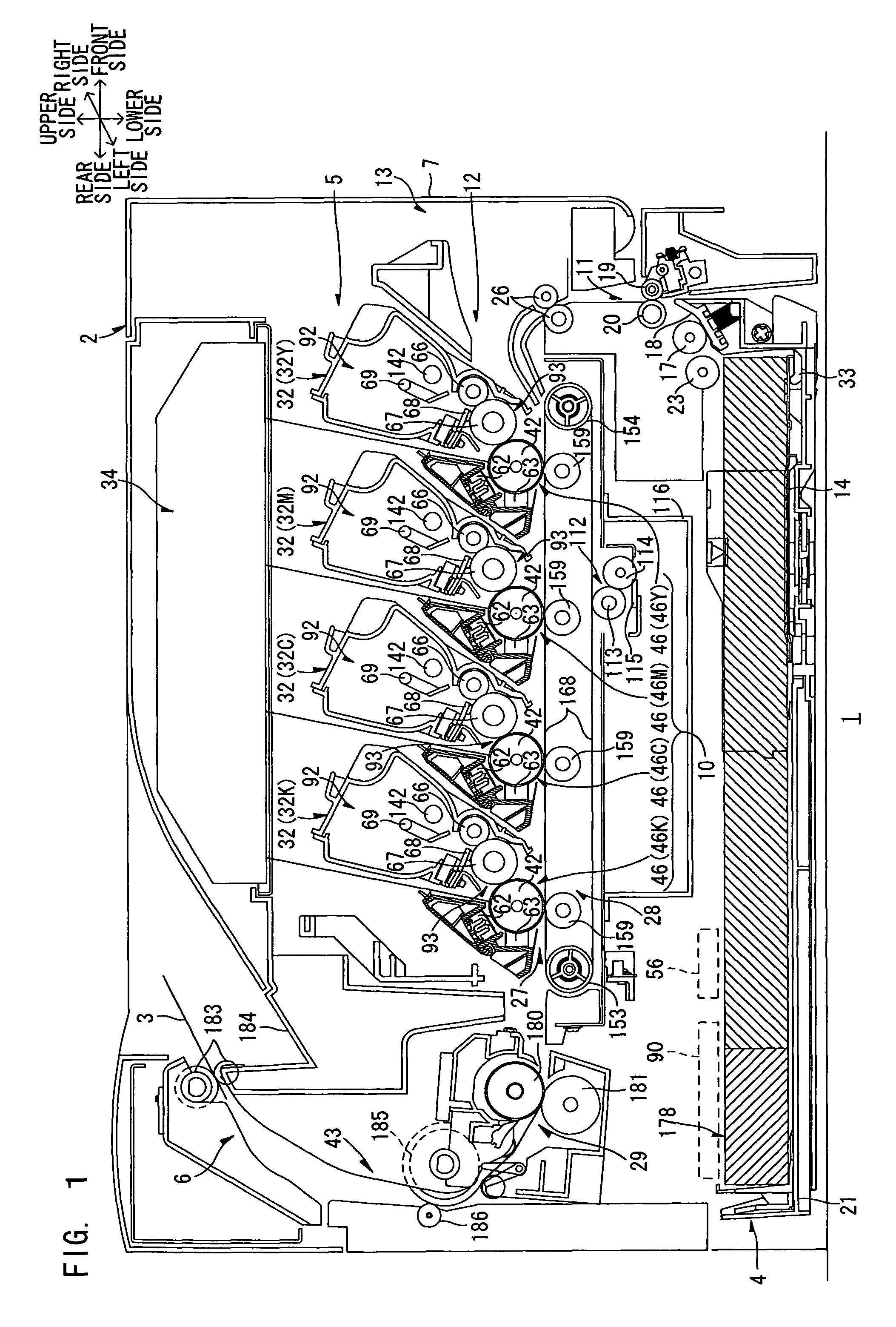
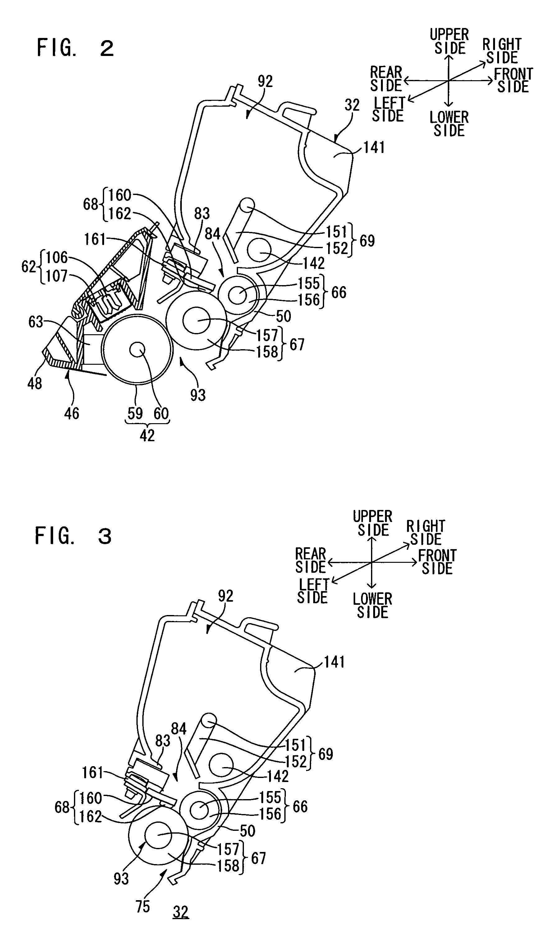
[0034]FIG. 1 is a sectional side elevation illustrating a major portion of a color laser printer as an image forming apparatus according to one embodiment of the present invention, and FIG. 2 is a sectional side elevation of a major portion of a drum subunit of the color laser printer of FIG. 1 in which a developer cartridge is mounted. FIG. 3 is a sectional side elevation of a major portion of the developer cartridge shown in FIG. 2, and FIG. 4 is a left perspective view of a processing section of the color laser printer of FIG. 1.

[0035]In FIG. 1, the color laser printer 1 is a tandem color laser printer of a horizontal type, in which a plurality of drum subunits 46 are horizontally arranged in tandem. The color laser printer 1 includes a sheet feeding section 4 for feeding a sheet 3 (recording medium), an image forming section 5 for forming an image on the fed sheet 3, and a sheet ejecting section 6 for ejecting the sheet 3 formed with...

second embodiment

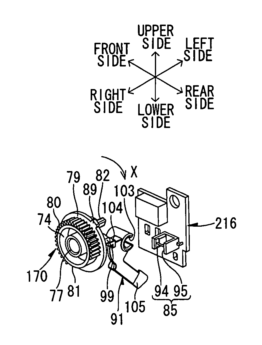
[0186]In the first embodiment, the information on the maximum image formation sheet number of the developer cartridge 32 is predefined by the number of the abutment projections 82, but may be predefined by the width of the abutment projection 82 as shown in FIGS. 15-1 and 15-2.

[0187]For example, the abutment projection 82 is designed as having a greater width as shown in FIGS. 15-1 and 15-2 to provide information indicating that the maximum image formation sheet number is 6000, and as having a smaller width as shown in FIGS. 13-1 and 13-2 to provide information indicating that the maximum image formation sheet number is 3000.

[0188]The CPU 90 is adapted to determine the maximum image formation sheet number on the basis of duration of the light block signal inputted from the optical sensor 85 as measured from the start of the driving of the motor 56.

[0189]Where the abutment projection 82 of the detection gear 170 has a smaller width as shown in FIGS. 11(a-1) to 11(c-4), the optical se...

third embodiment

[0193]In the first embodiment, the information indicating that the maximum image formation sheet number is 6000 is defined by the provision of the two abutment projections 82, and the information indicating that the maximum image formation sheet number is 3000 is defined by the provision of the single abutment projection 82. Alternatively, the information indicating that the maximum image formation sheet number is 6000 may be defined by the provision of the single abutment projection 82, and the information indicating that the maximum image formation sheet number is 3000 may be defined by the provision of the two abutment projections 82.

[0194]Although it is also possible to define the information on the maximum image formation sheet number of the developer cartridge 32 by the width of the abutment projection 82 as described above, the widths and number of the abutment projections 82 may be used in combination to define information other than the information on the maximum image form...


PUM


Abstract

When a developer cartridge is mounted together with a drum unit in a main body casing, a detection gear is rotated by driving of a motor, and an abutment projection of the detection gear is brought into abutment against a lever of a drum subunit to move the lever. The movement of the lever is detected by an optical sensor. A CPU judges information on the developer cartridge on the basis of the results of the detection by the optical sensor. Therefore, the information on the developer cartridge can be judged with a simple construction at reduced costs. Further, the developer cartridge can be mounted in the main body casing in spaced relation, so that the design flexibility is increased.

Description

CROSS REFERENCE TO RELATED APPLICATION[0001]This application claims priority benefits on the basis of Japanese Patent Application No. 2005-229905 filed on Aug. 8, 2005, the disclosure of which is incorporated herein by reference.BACKGROUND OF THE INVENTION[0002]1. Field of the Invention[0003]The present invention relates to an image forming apparatus (e.g., a laser printer), and to a developer cartridge to be removably mounted in the image forming apparatus.[0004]2. Description of the Related Art[0005]Conventionally, a developer cartridge which contains a toner is removably mounted in a laser printer. Such a laser printer includes new cartridge detection unit which judges whether or not the mounted developer cartridge is new and determines the service life of the new developer cartridge.[0006]New cartridge detection unit proposed, for example, in Japanese Unexamined Patent Publication No. 2000-221781 includes a sector gear provided in a developer cartridge and having a projection an...

Claims


Application Information

Patent Timeline
Patent Type & Authority Patents(United States)
IPC IPC(8): G03G15/00G03G15/04G03G21/18
CPCG03G15/553G03G21/1896G03G15/0868G03G15/55G03G15/0848G03G2215/0695G03G2221/1838G03G2221/1815
Inventor KAMIMURA, NAOYA
Owner BROTHER KOGYO KK
Why Eureka
Try Eureka