
Crimping press

a crimping press and press body technology, applied in forging/pressing/hammering apparatus, forging/hammering/pressing machines, metal-working feeding devices, etc., can solve the problem of readjusting the advancing uni

Active Publication Date: 2010-07-20
KOMAX HOLDING
View PDF6 Cites 1 Cited by
  • Summary
  • Abstract
  • Description
  • Claims
  • Application Information

AI Technical Summary

Benefits of technology

[0004]It is here that the present invention sets out to provide a remedy. The present invention provides a solution for avoiding the disadvantages of the known device, and creating a device and a method that make changing over to different crimp contacts, or to different contact distances in the contact belt, or to different belt widths, easy.
[0005]The advancing device can process contact belts with different contact distances without difficulty. By exchanging the exchangeable part, especially the contact-specific anvil part, the advancing device is automatically adapted to different widths of belt. Advancing of the contact belt by means of the advancing device depends on friction, by means of which the contact belt is gripped and advanced. The exact positioning and fixing of the crimp contacts during the crimping operation takes place in the anvil part by means of pins that engage in transport holes of the contact belt. Thanks to the simple changeover, especially changeover time and setting errors can be avoided, which in turn has a favorable effect on the production costs especially of many small production lots.
[0006]In the device according to the present invention, the contact advancer has a gripper that is independent of the distance between the transport holes and the width of the contact belt and that advances the contact belt as far as the exchangeable anvil part, a belt guide being provided on the exchangeable anvil part for fine positioning and holding of the contact belt.

Problems solved by technology

A disadvantage of this crimping press is that when changing to different crimp contacts and different contact distances in the crimp contact belt, the advancing unit must be readjusted.

Method used


Image

  • Crimping press
  • Crimping press
  • Crimping press

Examples


Embodiment Construction

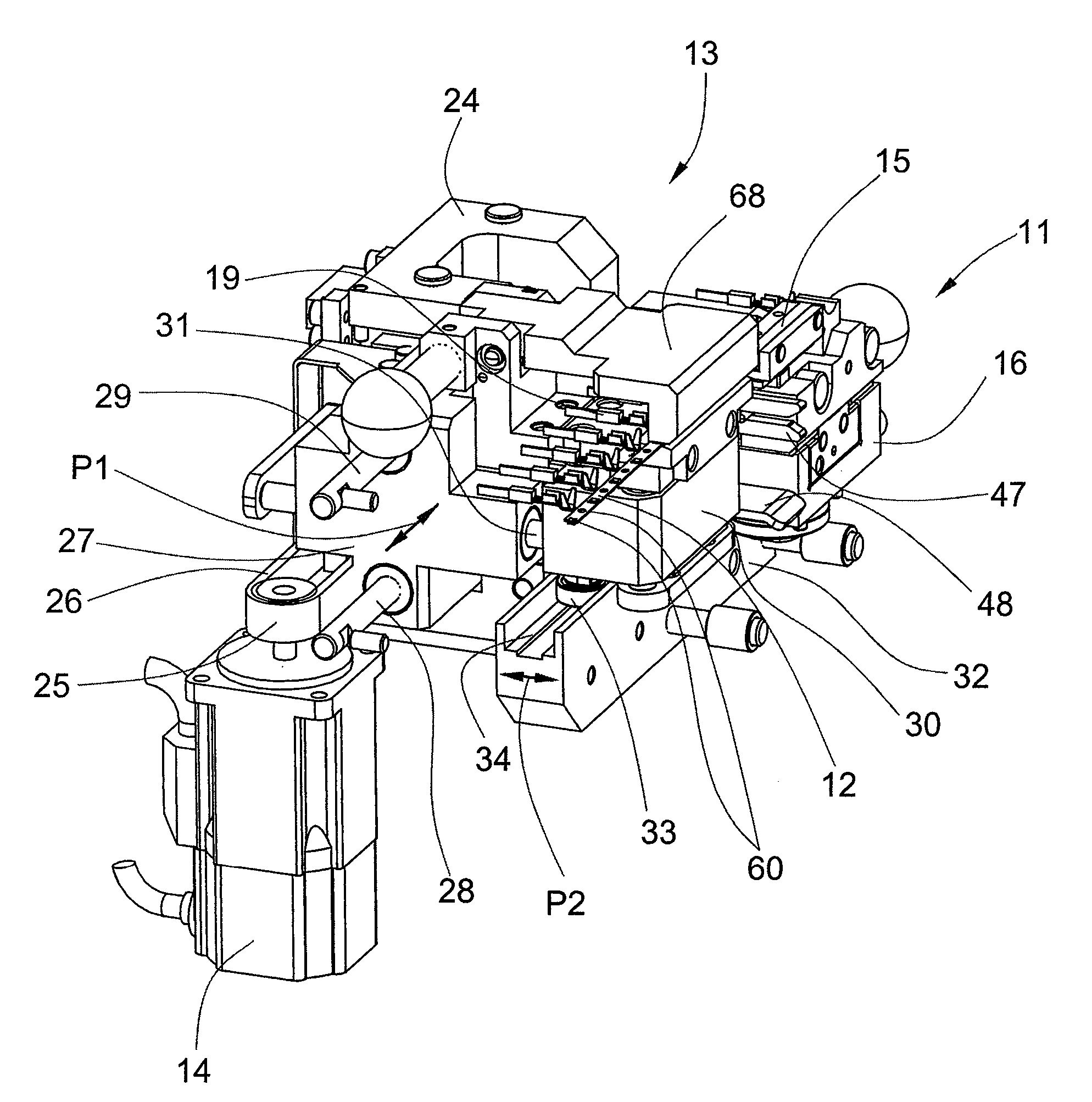
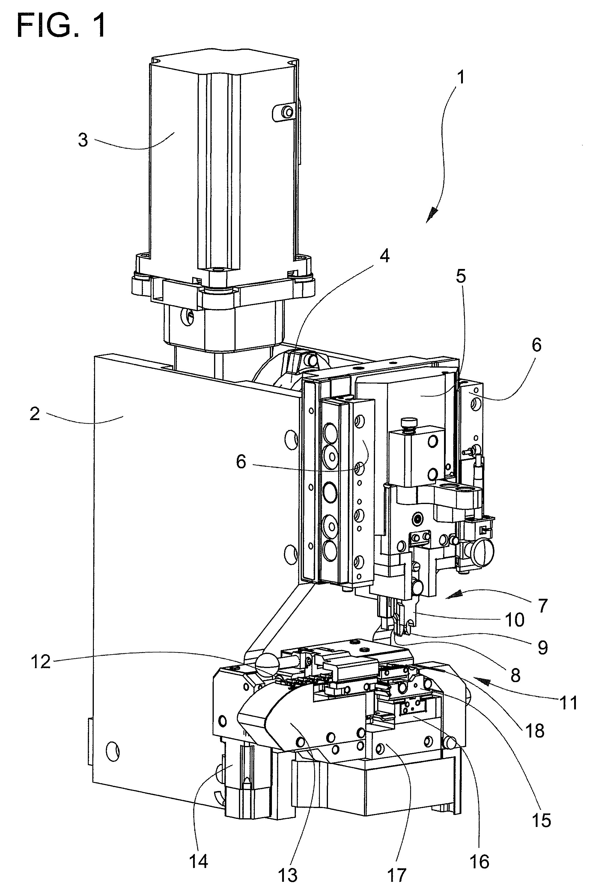
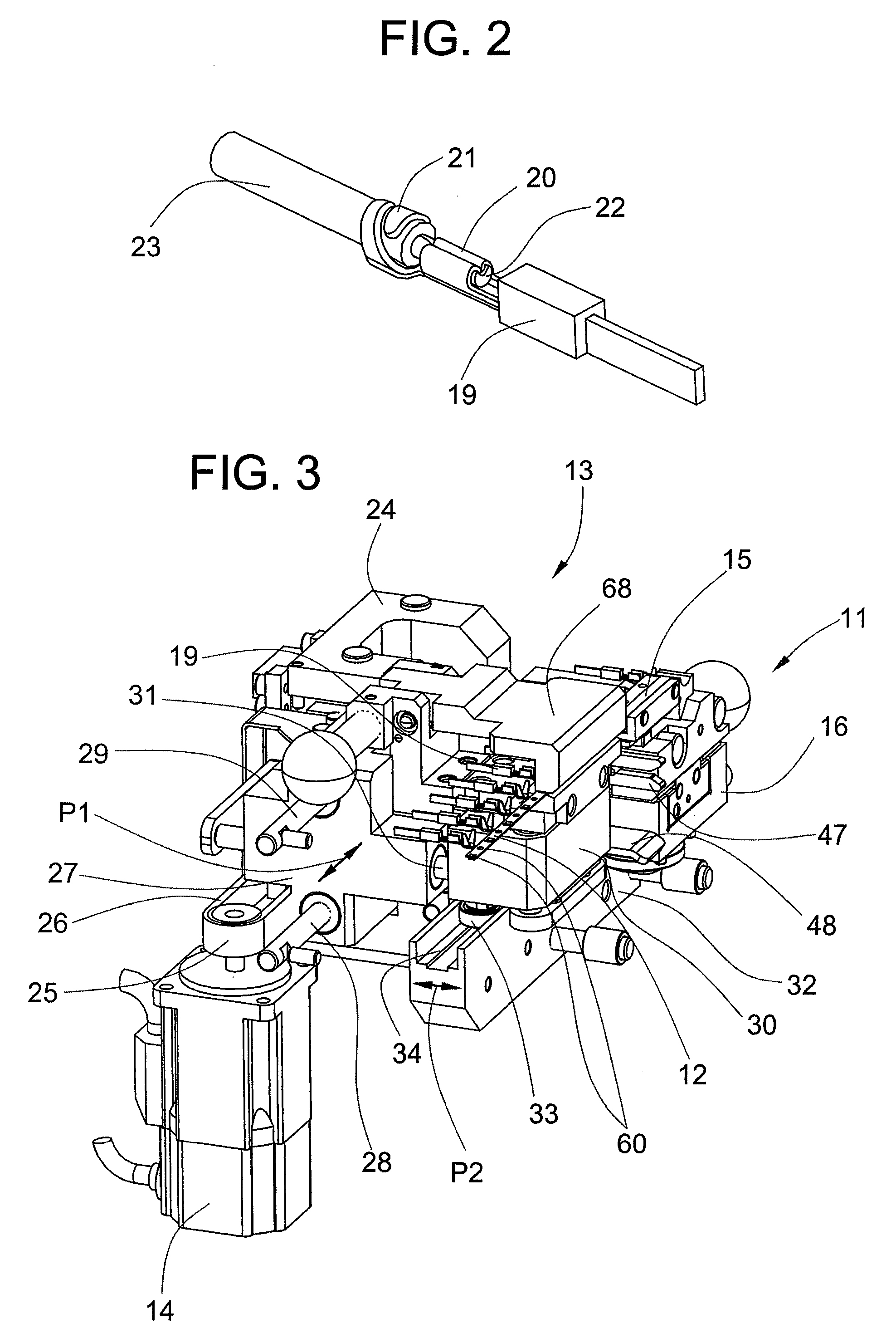
[0014]FIG. 1 shows a crimping press 1 according to the present invention comprising a first housing 2 on which a press motor 3 that drives a gear 4 is arranged. Provided on the output side of the gear is an eccentric device that converts the rotational motion of the motor 3 and the gear 4 into a linear up-and-down motion that can be transferred to a press carriage 5, the press carriage 5 being guided by means of guides 6. Provided for the production of a crimped fastening between a crimp contact 19 (FIG. 2) and a wire 18, and arranged on the press carriage 5, is an upper tool 7 with a conductor crimper 8, an insulation crimper 9, and a cutter plunger 10, the upper tool 7 working in conjunction with a lower tool 11. The lower tool 11 comprises an exchangeable part of an anvil 15, a sensor part 16, and a first supporting part 17. The crimp contacts 19 to be processed are parts of a contact belt 12 that is advanced by means of a contact advancer 13. An advancing motor 14 drives the con...


PUM

PropertyMeasurementUnit
widthaaaaaaaaaa
pressureaaaaaaaaaa
transport hole distanceaaaaaaaaaa

Abstract

A crimping device has a contact advancer provided with an exchangeable anvil part. A first pulley, a belt and an advancing motor drive a first carriage. A gripper for advancing the contact belt is guided in a direction crosswise to a direction of the first carriage. The distance between the gripper and the first carriage is determined by a second carriage and a roller of the gripper rolling in a fifth linear guide of the second carriage. The distance from the gripper is predetermined by the exchangeable anvil part and depends on the width of the contact belt. The gripper operates independent of the distance between the transport holes and independent of the width of the contact belt. The anvil part including the belt guide is an exchangeable part and only fits one type of crimp contact and is executed crimp-contact specifically.

Description

BACKGROUND OF THE INVENTION[0001]The present invention relates to a crimping press and a method of fastening belted crimp contacts to wires by means of crimpers and an exchangeable anvil part, a contact advancer advancing a contact belt that carries the crimp contacts as far as the exchangeable anvil part.[0002]There is shown in European patent specification EP 1 029 387 B1 a crimping press by which an electrical contact can be fastened onto the end of a wire. A crimping punch in conjunction with a crimping anvil fastens the crimp contact to the end of the wire. An advancing unit with an advancing element can be moved backward and forward between two stops. With every backward and forward movement of the advancing element, the crimp contact belt is advanced further toward the crimping anvil.[0003]A disadvantage of this crimping press is that when changing to different crimp contacts and different contact distances in the crimp contact belt, the advancing unit must be readjusted. The...

Claims


Application Information

Patent Timeline
Patent Type & Authority Patents(United States)
IPC IPC(8): H01R43/055
CPCH01R43/055Y10T29/49185Y10T29/53261Y10T29/5327Y10T29/53235
Inventor IMGRUT, PETERSPECK, MARC
Owner KOMAX HOLDING
Learn More