Vibration-induced die detachment system

a technology of vibration-induced die and detachment system, which is applied in the field of vibration-induced die detachment system, can solve the problems of die breaking or cracking, more problems, and more problems, and achieve the effect of reducing the risk of cracking and deformation of adhesive tap

Active Publication Date: 2010-07-20
ASM ASSEMBLY AUTOMATION LTD
View PDF8 Cites 33 Cited by
  • Summary
  • Abstract
  • Description
  • Claims
  • Application Information

AI Technical Summary

Benefits of technology

[0008]It is thus an object of this invention to seek to provide a die detachment system for detaching thin dice from an adhesive tape on which the dice are mounted with reduced risk of cracking and deformation of the adhesive tape, while avoiding some of the disadvantages of the aforesaid prior art.

Problems solved by technology

When the dice get thinner, especially in the case of stacked dice in an electronic package, there is always a chance that a die may break or crack during the detachment process of the die from the plastic adhesive film.
The breakage of the die is primarily due to the fact that the stress induced by the pushing up of the pins reaches the critical failure bending stress of the die before the delamination of the interface between the die and the plastic adhesive film takes place.
This will be more problematic for (i) dice of bigger size, (ii) thinner dice, and (iii) attachments where there is a stronger adhesion force between the die and the plastic adhesive film.
The drawback to this method relates to the use of an ultrasonic vibrator such as a transducer horn, which requires optimization in relation to the geometry of an upthrow pin and the type of adhesive tape used.
Developing a customized application tool is necessary for different dice and adhesive tape combinations and this consumes a lot of time.

Method used


Image

  • Vibration-induced die detachment system
  • Vibration-induced die detachment system
  • Vibration-induced die detachment system

Examples


Embodiment Construction

[0018]The preferred embodiment of the present invention will be described hereinafter with reference to the accompanying drawings.

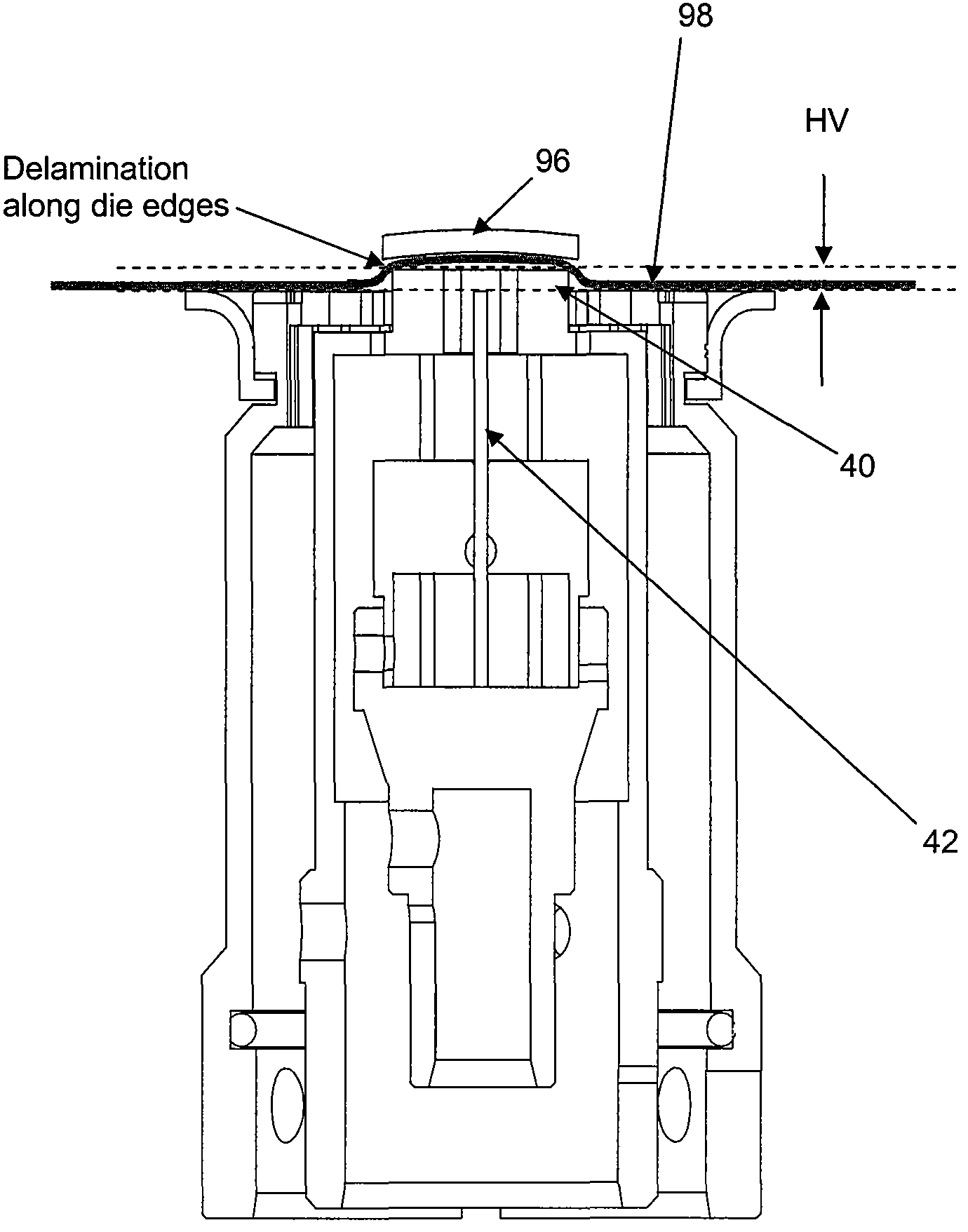
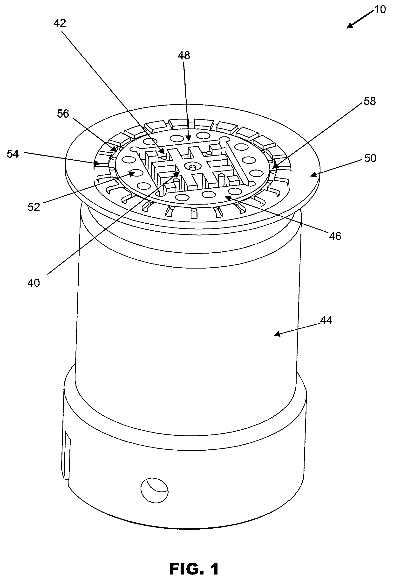
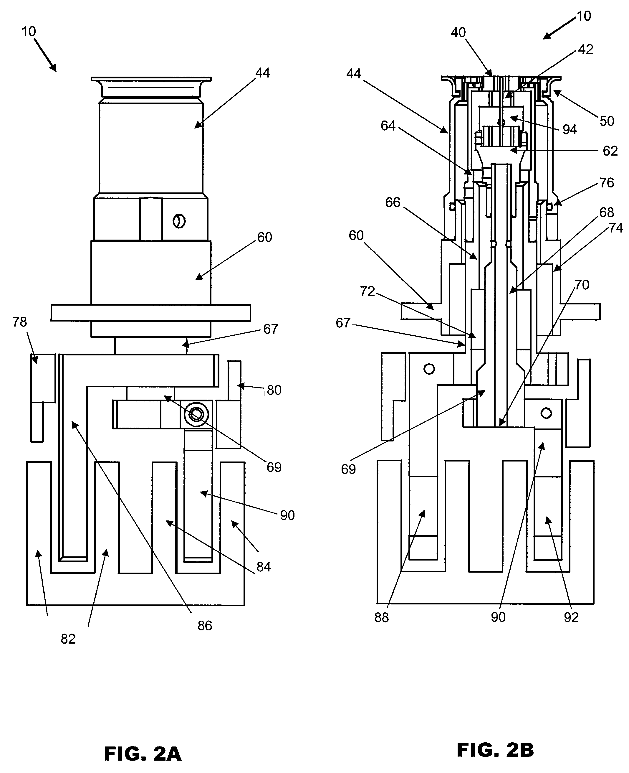
[0019]FIG. 1 is an isometric view of a die detachment tool according to the preferred embodiment of the present invention for detaching a thin die from an adhesive tape on which the die is mounted. The die detachment tool 10 comprises a vibrational tool 40 which may have a flat top surface, and ejector pins 42 which may have contact surfaces at their tips that are flat or rounded.

[0020]The ejector pins 42 and the vibrational tool 40 are located adjacent to one another and are both housed in a vacuum enclosure 44. They are projectable from the vacuum enclosure 44 to contact a portion of the adhesive tape at which the die is located to lift the die and adhesive tape. The surface of the vibrational tool 40 that contacts the adhesive tape may be in the shape of a grid. The vibrational tool 40 is operative to oscillate the adhesive tape and die for promoting d...


PUM

PropertyMeasurementUnit
sizesaaaaaaaaaa
distancesaaaaaaaaaa
distancesaaaaaaaaaa

Abstract

A die is detachable from an adhesive tape on which the die is mounted with a die detachment tool comprising a vacuum enclosure that is operative to provide a vacuum suction on the adhesive tape. One or more ejector pins are housed in the vacuum enclosure and are projectable from the vacuum enclosure for lifting the die and adhesive tape. A vibrational tool is housed in the vacuum enclosure adjacent to the ejector pins and it is projectable from the vacuum enclosure to contact a portion of the adhesive tape at which the die is located. The vibrational tool is further operative to oscillate the adhesive tape and die for promoting delamination of the die from the adhesive tape.

Description

FIELD OF THE INVENTION[0001]The present invention relates to a system for detaching a semiconductor die from an adhesive medium, and in particular, to a system for detaching a thin die from an adhesive tape on which it is mounted.BACKGROUND AND PRIOR ART[0002]In a typical die bonding process, semiconductor dice are detached and lifted from a film frame comprising plastic adhesive film or a Mylar film and are then transferred to a substrate such as a lead frame or printed wiring board (PWB) substrate. Typically, in a pick-up process, a designated die will first be aligned and moved to a location where push-up pins will rise to raise the die from below while the plastic adhesive film is held down by vacuum suction. The die will be detached from the plastic adhesive film when the push-up pins rise to an appropriate level. A collet or pick-up tool which is positioned just above the top surface of the die provides vacuum suction to pick up the detached die from the plastic adhesive film ...

Claims


Application Information

Patent Timeline
Patent Type & Authority Patents(United States)
IPC IPC(8): B32B38/10
CPCH01L21/67132Y10S438/976Y10T156/1983Y10T156/1179Y10T156/1922Y10T156/1121
Inventor CHEUNG, YIU MINGCHOW, MAN KIT
Owner ASM ASSEMBLY AUTOMATION LTD
Why Eureka
Try Eureka