
FLADE fan with different inner and outer airfoil stagger angles at a shroud therebetween

Active Publication Date: 2010-07-20
GENERAL ELECTRIC CO
View PDF21 Cites 37 Cited by
  • Summary
  • Abstract
  • Description
  • Claims
  • Application Information

AI Technical Summary

Benefits of technology

[0011]The radially outer airfoils may outnumber the radially inner airfoils and particularly by a ratio in a range of 1.5:1 to about 4:1. The FLADE fan assembly having the different inner and outer stagger angles is particularly useful in a FLADE counter-rotating fan aircraft gas turbine engine. The FLADE counter-rotating fan aircraft gas turbine engine includes axially spaced-apart upstream and downstream or forward and aft counter-rotatable fans circumferenti

Problems solved by technology

This significantly decreases the weight of the engine.
One issue regarding engine efficiency is the desirability of equalizing fan rotor torque between the counter-rotatable fans.

Method used


Image

  • FLADE fan with different inner and outer airfoil stagger angles at a shroud therebetween
  • FLADE fan with different inner and outer airfoil stagger angles at a shroud therebetween
  • FLADE fan with different inner and outer airfoil stagger angles at a shroud therebetween

Examples


Embodiment Construction

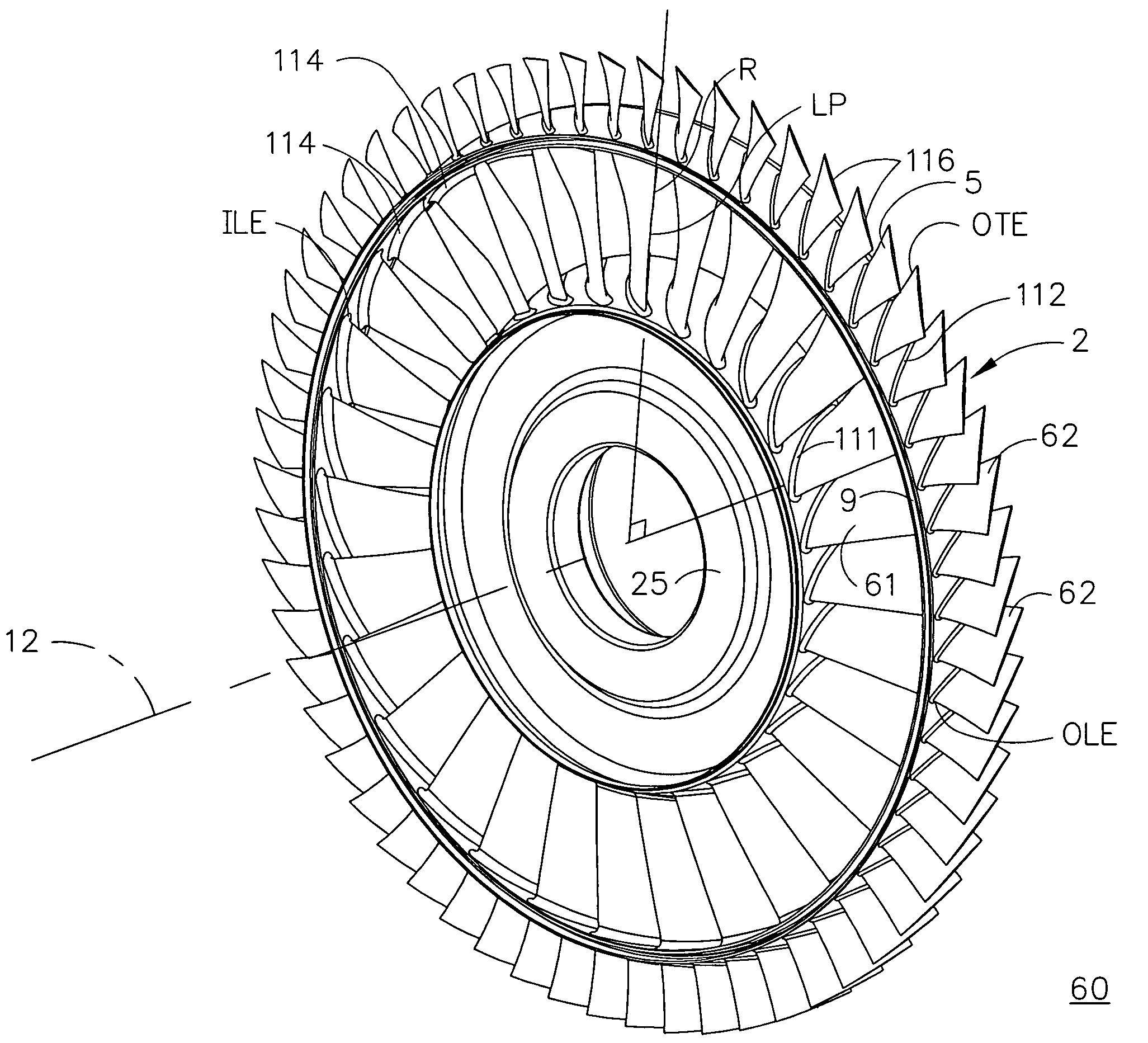
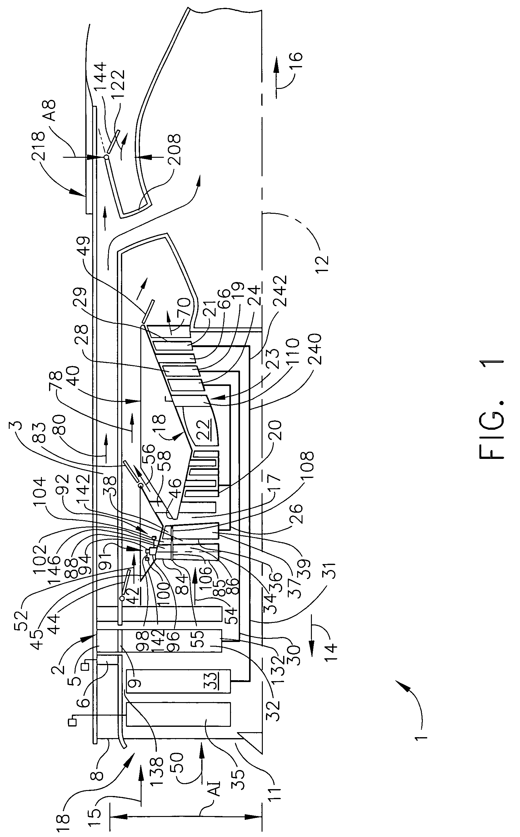
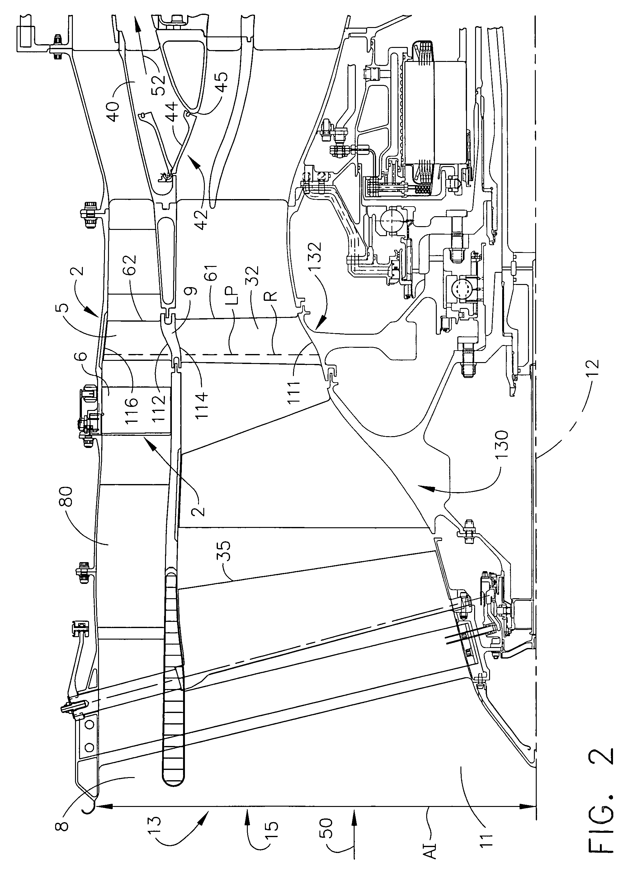
[0022]Illustrated in FIGS. 1-3 is a FLADE counter-rotating fan aircraft gas turbine engine 1 having a fan inlet 11 leading to upstream and downstream or forward and aft counter-rotatable fans 130, 132. A circumferential row of fan inlet guide vanes 35 is disposed between the fan inlet 11 and the forward counter-rotatable fan 130. The FLADE fan assembly 60 includes a FLADE fan 2 having at least one row of FLADE fan blades 5 disposed in a FLADE duct 3 through which FLADE airflow 80 is exhausted by the FLADE fan blades 5. The row of FLADE fan blades 5 is disposed radially outward of, operably connected to, and driven by one of the forward or aft counter-rotatable fans 130, 132. The FLADE fan blades 5 are disposed axially aft and downstream of variable FLADE inlet guide vanes 6. In FIG. 1, the aft fan 132 is illustrated as the FLADE fan having the row of FLADE fan blades 5. The FLADE fan 2 is disposed downstream of an annular FLADE inlet 8 to the FLADE duct 3. The FLADE inlet 8 and the ...


PUM


Abstract

A FLADE fan assembly includes radially inner and outer airfoils extending radially inwardly and outwardly respectively from an annular shroud circumferentially disposed about a centerline. Inner and outer chords extend between inner and outer leading and trailing edges of inner and outer airfoil cross-sections of the radially inner and outer airfoils respectively. Inner and outer stagger angles between the inner and outer chords respectively at the shroud and the centerline are different. The radially outer airfoils may outnumber the radially inner airfoils and particularly by a ratio in a range of 1.5:1 to about 4:1. Load paths or radii may extend radially through the inner and outer airfoils and through the rotating shroud between the inner and outer airfoils and may pass near or through the inner and outer leading edges and through the inner and outer trailing edges.

Description

[0001]The Government has rights in this invention pursuant to Contract No. F33615-03-D-2352 awarded by the Department of Defense.BACKGROUND OF THE INVENTION[0002]1. Field of the Invention[0003]This invention relates to FLADE aircraft gas turbine engines and, more particularly, to such engines with counter-rotatable fans.[0004]2. Description of Related Art[0005]High performance variable cycle gas turbine engines are being designed because of their unique ability to operate efficiently at various thrust settings and flight speeds both subsonic and supersonic. An important feature of the variable cycle gas turbine engine which contributes to its high performance is its capability of maintaining a substantially constant inlet airflow as its thrust is varied. This feature leads to important performance advantages under less than full power engine settings or maximum thrust conditions, such as during subsonic cruise.[0006]Counter-rotating fan gas turbine engines have also been designed an...

Claims


Application Information

Patent Timeline
IPC IPC(8): F01D1/26
CPCF01D5/022F02K3/077F02K3/072Y02T50/671Y02T50/673Y02T50/60
Inventor WADIA, ASPI RUSTOMTURNER, ALAN GLENDZIECH, AARON MICHAELSZUCS, PETER NICHOLASDECKER, JOHN JARED
Owner GENERAL ELECTRIC CO
Features
  • Generate Ideas
  • Intellectual Property
  • Life Sciences
  • Materials
  • Tech Scout
  • Unparalleled Data Quality
  • Higher Quality Content
  • 60% Fewer Hallucinations
Learn More