
Plug connector for use with a receptacle

a technology for plug connectors and receptacles, applied in the direction of electrical equipment, medical/surgical connectors, coupling device connections, etc., can solve the problems of inability to match visual indicia or shape, or may become difficult, and achieve the effect of convenient locking into place, easy mation and unmation, and low cos

Inactive Publication Date: 2010-07-20
CREGANNA UNLTD
View PDF31 Cites 29 Cited by
  • Summary
  • Abstract
  • Description
  • Claims
  • Application Information

AI Technical Summary

Benefits of technology

[0013]An advantage of the present invention is that the plug connector can provide an effective way to avoid a reuse of instrumentation designed for a single use. The plug connector can be provided for single use and made inexpensively, connected to the disposable instrumentation, and can be disposed of with the disposable instrumentation, if so desired.
[0014]Another advantage of the present invention is that the plug connector is easily mated to and unmated from the sophisticated medical equipment so that any protective gloves do not have to be removed, and is readily locked into place to prevent inadvertent disassembly. Furthermore, when single use is intended, full assembly of the plug contact into the mating receptacle captures the jumper contact into its second position, and further use of the plug connector does not result in movement of the jumper contact from its captured position.
[0015]Another advantage of the combined plug connector and mating receptacle is that the receptacle attached to the sophisticated equipment has a high cycle life, so that it can be reused significantly. The plug connector may be restricted substantially to a single use on insertion into a mating receptacle, if so desired.
[0016]Still another advantage of the combined plug connector and mating receptacle having a jumper contact is that the combination provides a signal indicative of the presence of a new plug connector, or at least a plug connector not previously inserted into a mating receptacle, and the sophisticated equipment can be programmed in a number of ways to react to the presence of a plug connector mated to the receptacle and the presence or absence of a signal indicative of a new or not previously used plug connector.

Problems solved by technology

In low light situations, visual indicia or shape matching may not be possible or may become difficult.

Method used


Image

  • Plug connector for use with a receptacle
  • Plug connector for use with a receptacle
  • Plug connector for use with a receptacle

Examples


Embodiment Construction

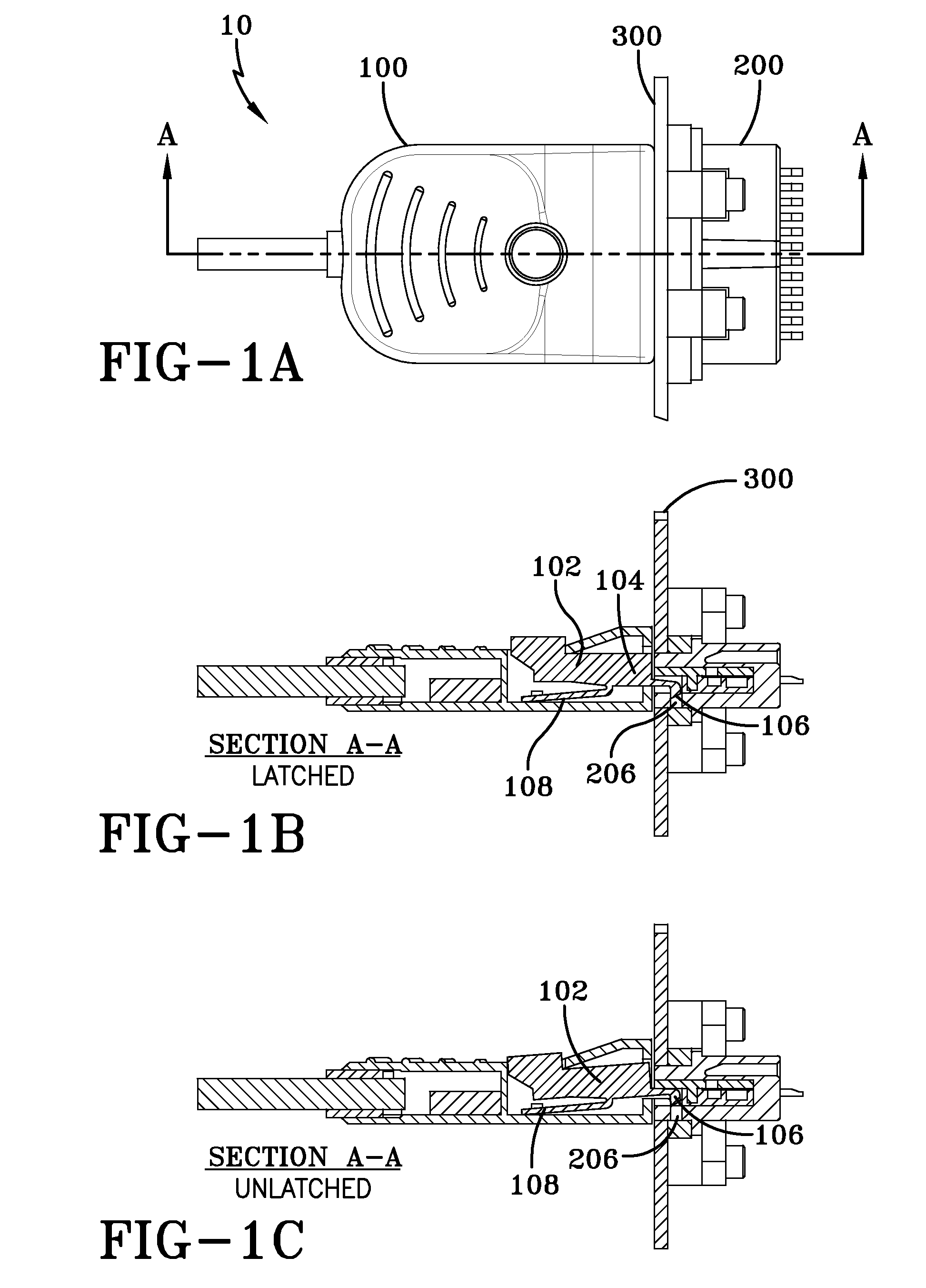
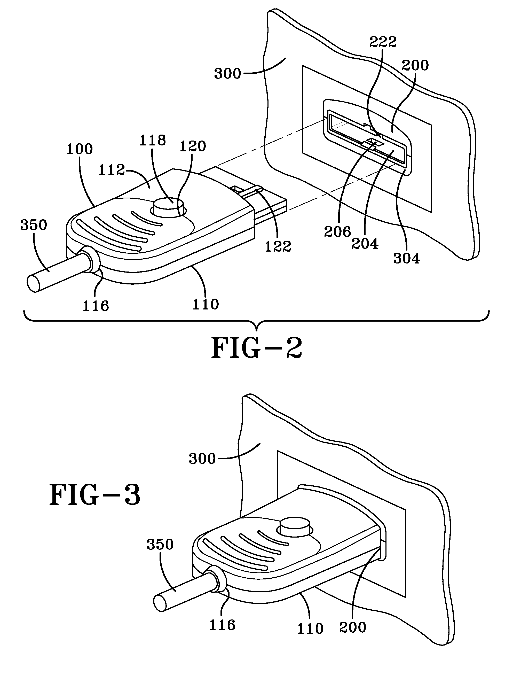
[0025]The present invention is depicted in FIG. 1, delineating a plug connector / receptacle assembly 10 of the present invention. The assembly having a plug connector 100 fitted to a receptacle 200. Such a plug connector optionally provides for plug connector 100 that can provide a single use, or be limited to a predetermined number of uses due to other factors such as the addition of electronics.

[0026]FIG. 1A depicts a top view of assembly 10, while FIG. 1B depicts a sectional view along section A-A of assembly 10 with plug connector 100 mated to receptacle 200 in the latched position. FIG. 1C depicts a sectional view along section A-A of assembly 10 with plug connector mated to receptacle 200 in the unlatched position. FIG. 1 depicts plug connector 100 as having a rectangular section at the end at which it mates with receptacle 200 and a somewhat rounded end opposite receptacle 200. This is a preferred geometry, and the shape of plug connector is not so limited. It is preferred, ho...


PUM


Abstract

A plug connector for use with a receptacle. The plug connector and receptacle combination may prevent more than one use of the single use plug connector, thereby necessitating disposal of the plug connector and associated, disposable, specialized instrumentation to which the plug connector is connected. The plug connector may be keyed and otherwise identified to the receptacle by shape, tactile indicia and visual indicia so that it cannot be mistakenly used with a different receptacle, while providing proper orientation for rapid assembly. When designed for single use or limited multiple use, the insertion of the plug connector into the receptacle moves a jumper contact in the plug connector from a first position to a second position where it is captured. The receptacle and plug connector may include an interface for a light pipe and a light path that illuminates the plug connector to facilitate assembly and disassembly in areas in which light is limited, such as operating rooms, as well as communicating information to the user.

Description

FIELD OF THE INVENTION[0001]The present invention is directed to a plug connector and receptacle combination for use with complex equipment, and in, particular, for use with equipment used for medical and dental applications.BACKGROUND OF THE INVENTION[0002]Because of various safety and sanitary concerns, instruments and equipment used for various dental and medical procedures are utilized for a single patient or a single event and then are disposed of or sterilized prior to reuse. However, not all equipment can or should be disposed of after a single use because of its sophistication and associated expense. This equipment may include delicate electronic instrumentation that monitors various patient conditions and should be reused. Such equipment may be isolated from biohazards because of its expense and inability to be sterilized after such an exposure. This type of equipment is to be distinguished from what is referred to herein as instrumentation, which may be complex, but which ...

Claims


Application Information

Patent Timeline
Patent Type & Authority Patents(United States)
IPC IPC(8): H01R13/627
CPCH01R13/6275H01R13/641H01R13/7172Y10S439/91H01R13/748H01R2201/12Y10S439/909H01R13/7175
Inventor MILLER, KEITH EDWINIRWIN, WILLIAM DAVIDBECK, TIMOTHY M.PATEL, NAVIN KANJIBHAI
Owner CREGANNA UNLTD
Learn More