
Illuminable basketball rim assembly and associated method

a basketball rim and assembly technology, applied in the field of portable basketball rims, can solve the problems of complex and difficult assembly of this invention, and not providing an illuminable rim, so as to achieve the effect of providing user enjoyment in space-limited areas

Inactive Publication Date: 2010-07-20
DIKES LAMAAR
View PDF9 Cites 9 Cited by
  • Summary
  • Abstract
  • Description
  • Claims
  • Application Information

AI Technical Summary

Benefits of technology

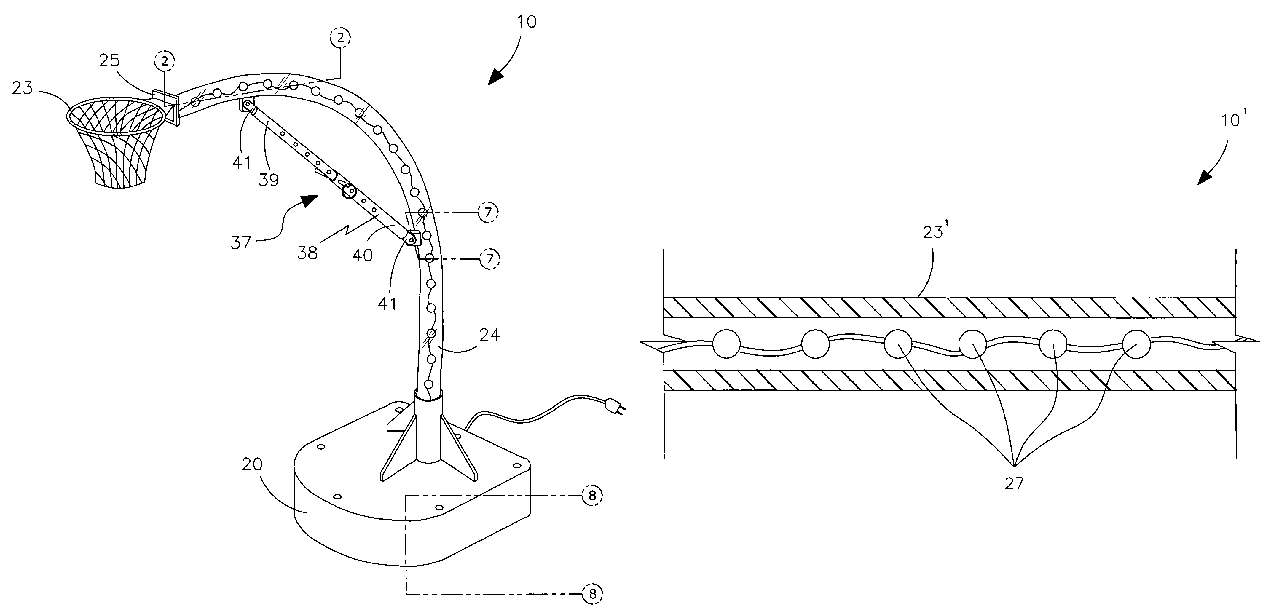
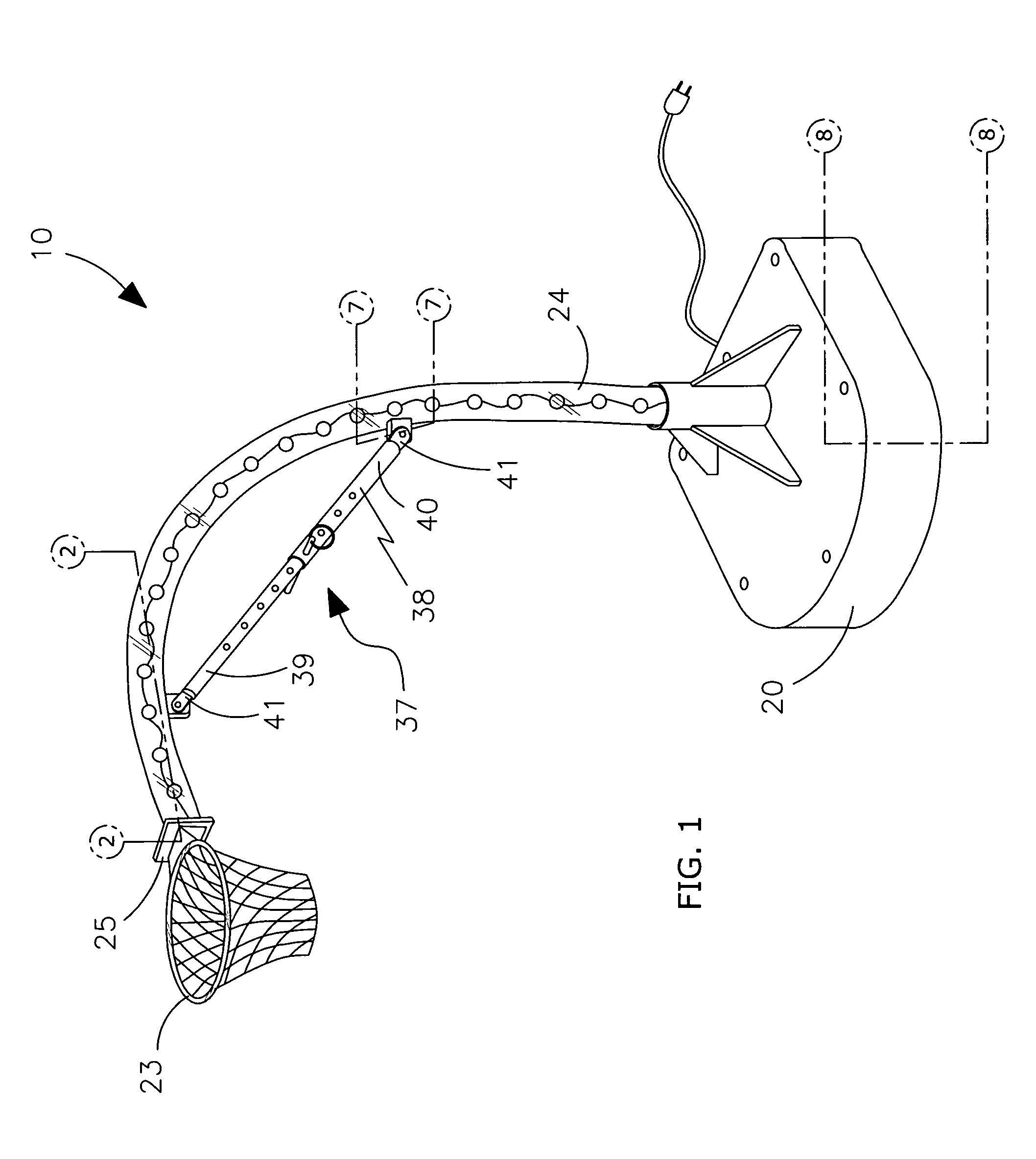
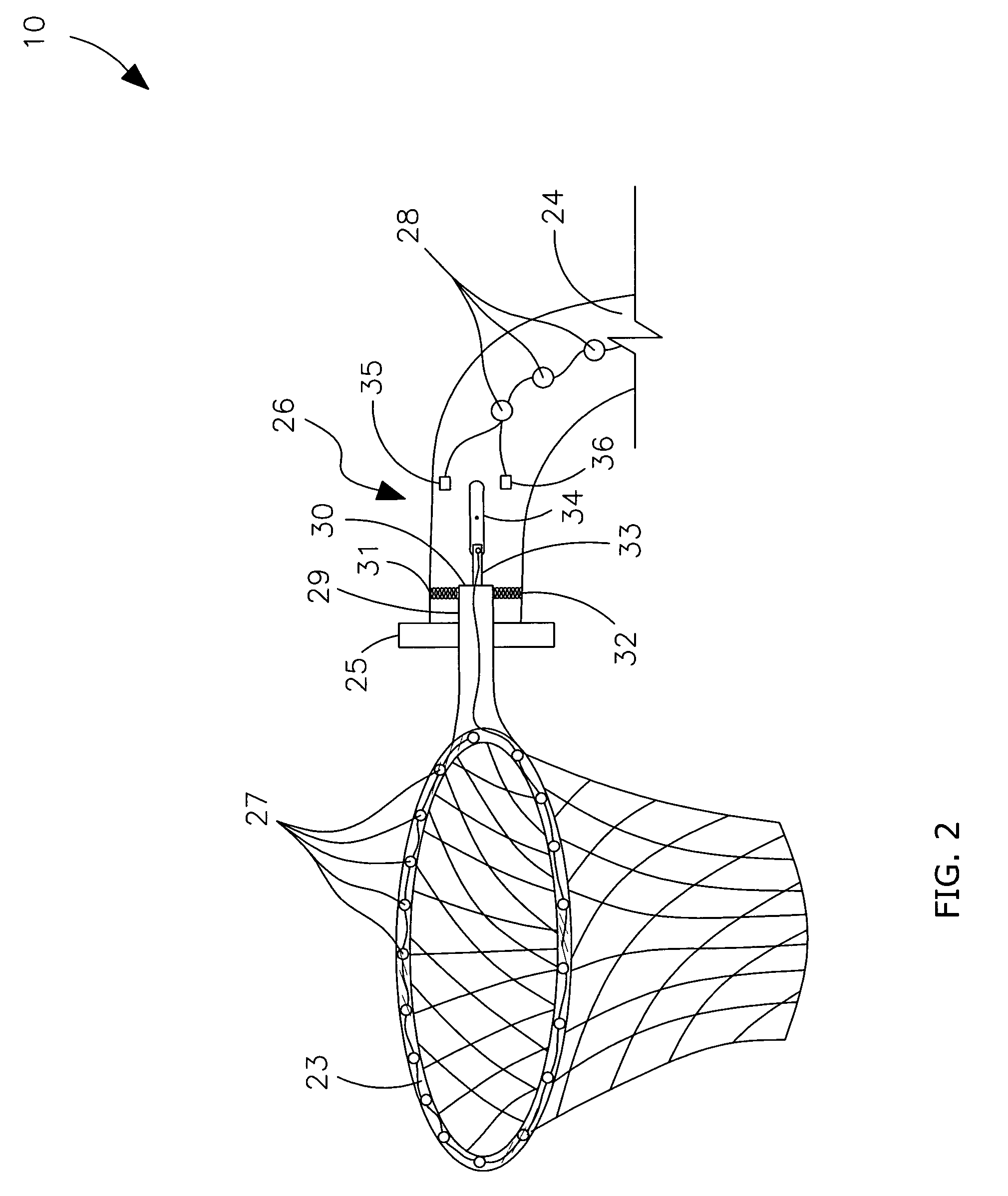
[0014]The assembly further includes a mechanism for effectively illuminating the rim section and the support pole when an external force is applied to the rim section. The rim section and the support pole illuminating mechanism includes a first plurality of illuminable elements effectively embedded within the rim section and traveling about an entire circumference thereof. A second plurality of illuminable elements is effectively embedded within the support pole and travels along a major longitudinal length thereof. An elongated flange advantageously extends rearwardly from the rim section and has a posterior end adjustably seated within the distal end of the support pole. First and second deformably resilient spring members are conveniently nested within the support pole and attached directly to the flange to thereby advantageously maintain the rim section at the equilibrium position effectively defined centrally within the support pole.
[0016]A mechanism advantageously maintains the support pole at a stable and equilibrium position such that the distal end of the support pole is effectively prohibited from displacing downwardly beyond a predefined height. Such a support pole maintaining mechanism includes a rectilinear shaft including telescopically engaged male and female members. Each of such male and female members includes a distal end pivotally attached to the support pole such that a longitudinal length of the shaft is advantageously maintained at a fixed position during operating conditions for effectively prohibiting the support pole from bending beyond a predetermined threshold. The distal end of the male member is conveniently disposed proximate to the distal end of the support pole.
[0018]The method further includes the steps of, providing a first plurality of illuminable elements embedded within the rim section and traveling about an entire circumference thereof, providing a second plurality of illuminable elements embedded within the support pole and traveling along a major longitudinal length thereof, providing an elongated flange extending rearwardly from the rim section that has a posterior end adjustably seated within the distal end of the support pole, and providing first and second deformably resilient spring members nested within the support pole and attached directly to the flange to thereby maintain the rim section at the equilibrium position defined centrally within the support pole.

Problems solved by technology

Unfortunately, this prior art example does not provide an illuminable rim for allowing a player to use the rim during low light conditions.
In addition, due to the number of elements involved, the assembly of this invention is complicated and difficult.
Unfortunately, this prior art example also does not provide an illuminable rim.
In addition, this example does not allow a user to attach the rim to the support pole through the use of a magnetized attachment pin.

Method used


Image

  • Illuminable basketball rim assembly and associated method
  • Illuminable basketball rim assembly and associated method
  • Illuminable basketball rim assembly and associated method

Examples


Embodiment Construction

[0039]The present invention will now be described more fully hereinafter with reference to the accompanying drawings, in which a preferred embodiment of the invention is shown. This invention may, however, be embodied in many different forms and should not be construed as limited to the embodiment set forth herein. Rather, this embodiment is provided so that this application will be thorough and complete, and will fully convey the true scope of the invention to those skilled in the art. Like numbers refer to like elements throughout the figures.

[0040]The assembly of this invention is referred to generally in FIGS. 1-15 by the reference numeral 10 and 10′ is intended to provide an illuminable portable basketball rim that does not employ a backboard. It should be understood that the assembly 10 and 10′ may be used in various environments and should not be construed as limited to an outdoor basketball rim assembly.

[0041]Referring to FIGS. 1, 2, 3, 4, 5, 6, 8, 9 and 14, the assembly 10 ...


PUM


Abstract

An illuminable basketball rim assembly includes an anchor member that has a hollow cavity filled with a weight agent. A support pole is coupled to the anchor member and extends upwardly therefrom, and has a distal end positioned anterior to the anchor member. A rim section is positioned at the distal end of the support pole. A mechanism illuminates the rim section and the support pole when an external force is applied to the rim section. A mechanism maintains the support pole at a stable and equilibrium position such that the distal end of the support pole is prohibited from displacing downwardly beyond a predefined height.

Description

CROSS REFERENCE TO RELATED APPLICATIONS[0001]This application claims the benefit of U.S. Provisional Application No. 60 / 772,962, filed Feb. 13, 2006, the entire disclosures of which are incorporated herein by reference.STATEMENT REGARDING FEDERALLY SPONSORED RESEARCH OR DEVELOPMENT[0002]Not Applicable.REFERENCE TO A MICROFICHE APPENDIX[0003]Not Applicable.BACKGROUND OF THE INVENTION[0004]1. Technical Field[0005]This invention relates to portable basketball rims and, more particularly, to an illuminable portable basketball rim that does not employ a backboard.[0006]2. Prior Art[0007]The game of basketball is played by many people throughout the United States and the world. Briefly, the game of basketball includes a flat and level playing surface with a basketball goal at each end of the court. The basketball goal typically includes a support pole with a backboard and rim or hoop attached to the top of the support pole. The rim or hoop is normally located ten feet above the playing su...

Claims


Application Information

Patent Timeline
Patent Type & Authority Patents(United States)
IPC IPC(8): A63B63/08
CPCA63B63/08A63B63/083A63B2207/02A63B2225/74
Inventor DYKES, LAMAAR
Owner DIKES LAMAAR
Learn More