Water disposal system using an engine as a water heater

a technology of water heater and water disposal system, which is applied in the direction of separation process, waste water treatment from quaries, borehole/well accessories, etc., to achieve the effect of efficient heating of air

Active Publication Date: 2019-12-24
SHERRY RAYMOND C
View PDF29 Cites 4 Cited by
  • Summary
  • Abstract
  • Description
  • Claims
  • Application Information

AI Technical Summary

Benefits of technology

[0014]The utilization of an internal combustion engine at the well site for generating electrical and mechanical power necessarily involves the production of engine emissions. According to an advantage of the invention, the engine exhaust is released into the duct along with the production water which effectively disposes of the exhaust particulate matter and contains the same. In some embodiments, the engine exhaust can be released into the production water to effectively embed the emission gasses and solids in the production water. At the same time, the production water is heated for better forming into the vapor phase.
[0015]A further embodiment of the invention includes an internal combustion engine that is located inside the duct so that any and all of the thermal energy radiated from the engine is imparted to the incoming air, thereby efficiently heating the air.
[0016]Other features and advantages are set forth in the following description. Accordingly, the features and advantages listed above represent only some and not all of the features.

Problems solved by technology

The production water that returns to the surface is contaminated with other toxic substances and a significant mineral content, all that must be considered.

Method used


Image

  • Water disposal system using an engine as a water heater
  • Water disposal system using an engine as a water heater
  • Water disposal system using an engine as a water heater

Examples


Embodiment Construction

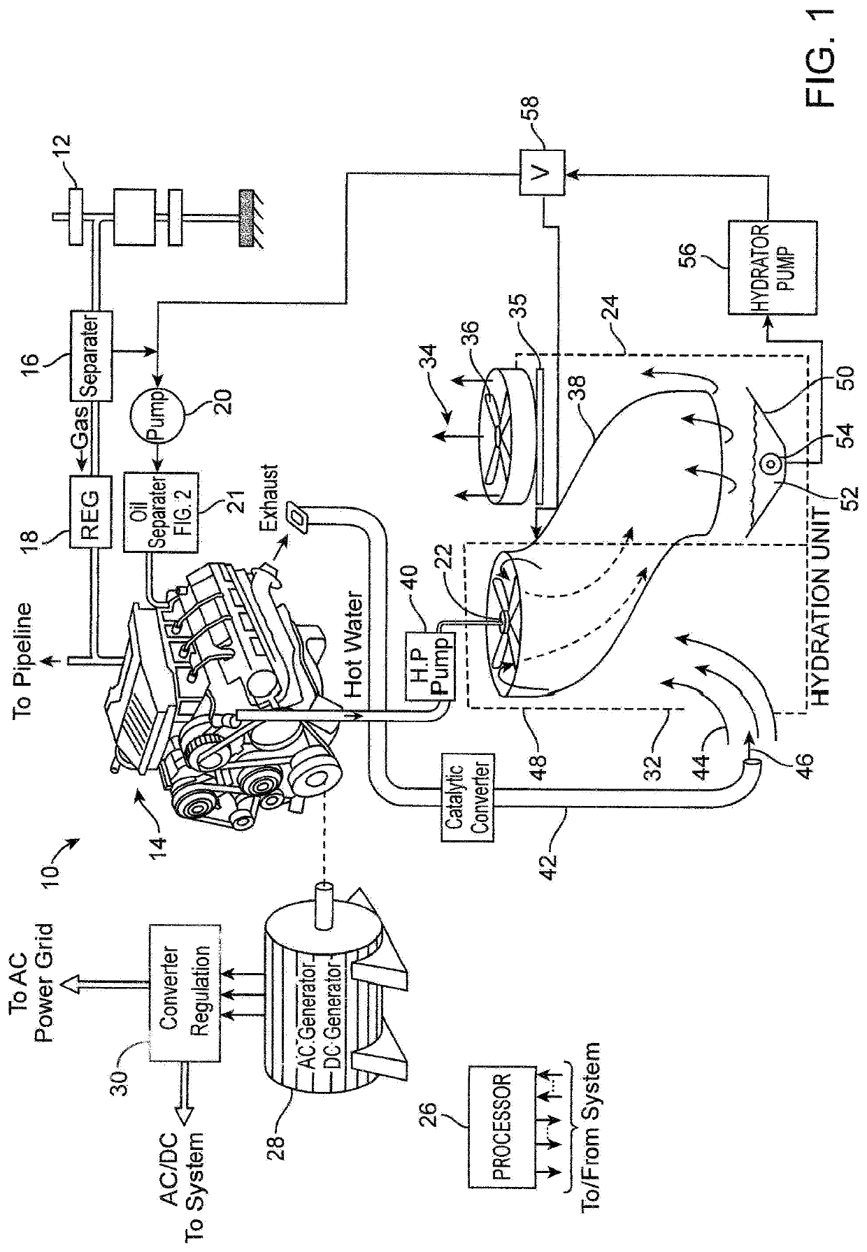
[0023]With reference to FIG. 1 of the drawings, there is illustrated the major components of the water disposal system 10 which processes production water from a gas wellhead 12, and disposes of the water content by hydrating the atmospheric air. In this manner, a significant amount of the water is disposed of without having to haul it to a disposal well or otherwise dispose of it. Not only is the hauling cost saved, but the system uses the thermal energy generated by an internal combustion engine 14 to heat the production water. The thermal energy generated by the engine 14 would otherwise be lost to the atmosphere. With this arrangement, the engine 14 does not require a coolant radiator as do conventional internal combustion engines, and the system 10 does not require a high energy heater / burner.

[0024]In more detail, the liquid and gasses available at the wellhead 12 are under pressure and are coupled to a conventional separator 16 which separates the liquid content (oils and the ...


PUM

PropertyMeasurementUnit
pressureaaaaaaaaaa
pressureaaaaaaaaaa
diameteraaaaaaaaaa

Abstract

A water hydration system for disposing of the water content of the production water recovered from a hydrocarbon well. An internal combustion engine is utilized to drive electrical generators, pumps, etc., to provide electrical and mechanical power to the equipment of the well site. The engine includes a cooling system through which preprocessed production water flows to elevate the temperature thereof. The heated water is then sprayed into hot air to hydrate the air before being released to the atmosphere.

Description

RELATED APPLICATION[0001]This U.S. non-provisional patent application claims the benefit of U.S. provisional application Ser. No. 62 / 496,946, filed Nov. 2, 2016.TECHNICAL FIELD OF THE INVENTION[0002]The present invention relates in general to water processing systems, and more particularly to methods and apparatus for more efficiently processing production water produced from gas wells by using the thermal energy generated by an engine as a source of heat to heat the production water during processing thereof to dispose of the same.BACKGROUND OF THE INVENTION[0003]Gas wells are developed by drilling a borehole in a formation where the natural gas is believed to exist. The borehole is then fractured by forcing a high pressure liquid, such as water, into the borehole to create fractures throughout the formation and allow the pressurized gas to migrate to the borehole and thus be retrieved at the surface. It often requires a million gallons of water, or more, to carry out the fracturin...

Claims


Application Information

Patent Timeline
Patent Type & Authority Patents(United States)
IPC IPC(8): C02F1/06B01D1/16C02F1/04E21B41/00B05B1/30C02F101/32C02F103/10
CPCC02F1/06E21B41/005C02F1/048B01D1/16B05B1/3006C02F2101/32C02F2201/009C02F2303/10C02F2103/10C02F2301/04B01D1/0058B01D1/14C02F1/16E21B41/00Y02W10/37
Inventor SHERRY, RAYMOND C.
Owner SHERRY RAYMOND C
Why Eureka
Try Eureka