Pump set with secure loading features

a technology of loading feature and pump, which is applied in the field of pump sets, can solve the problem that the pump may deliver an inaccurate amount of fluid to a patient, and achieve the effect of improving the safety of patients

Active Publication Date: 2010-07-20
KPR U S LLC
View PDF193 Cites 15 Cited by
  • Summary
  • Abstract
  • Description
  • Claims
  • Application Information

AI Technical Summary

Benefits of technology

[0004]In one aspect of the present invention, a feeding set is used in an enteral feeding pump having a control system for controlling operation of the enteral feeding pump to supply liquid nutrient to a patient through the feeding set loaded in the pump, a source of infrared radiation operatively connected to the control system of the pump for emitting infrared radiation, an infrared radiation detector operatively connected to the control system for detecting infrared radiation and providing an indication that the feeding set is properly loaded on the pump, and a visible light detector for detecting visible light and providing an indication that the feeding set is not properly loaded on the pump. The feeding set generally comprises a conduit for carrying the liquid nutrient to a patient. A safety interlock device connected to the conduit is adapted for mounting on the pump in the path of the infrared radiation from the source of infrared radiation. The safety interlock device comprises a propagation affecting member including an outer member formed of a material that transmits infrared radiation and blocks visible light and an inner member defining an inner boundary region that substantially reflects the infrared radiation within the propagation affecting member to change the direction of propagation. Upon proper loading of the safety interlock device on the pump, the safety interlock device guides infrared radiation to the first detector and prevents visible light from reaching the second detector.
[0006]In yet another aspect of the present invention, a pump set is used in a pumping apparatus having a control system for controlling operation of the pumping apparatus to supply fluid to a patient through the pump set loaded in the pump, a source of electromagnetic radiation operatively connected to the control system of the pump for emitting electromagnetic radiation, a first electromagnetic radiation detector operatively connected to the control system for detecting electromagnetic radiation generally of a first wavelength and providing an indication that the pump set is properly loaded on the pumping apparatus, and a second electromagnetic radiation detector for detecting electromagnetic radiation generally of a second wavelength different from the first wavelength and providing an indication that the pump set is not properly loaded on the pumping apparatus. The pump set generally comprises a conduit for carrying fluid to a patient. A safety interlock device associated with the conduit and adapted for mounting in the pumping apparatus in the path of the electromagnetic radiation from the source of electromagnetic radiation is adapted to transmit electromagnetic radiation of the first wavelength, and adapted not to transmit the electromagnetic radiation of the second wavelength. Therefore, upon proper loading of the safety interlock device on the pumping apparatus the safety interlock device guides electromagnetic radiation of the first wavelength to the first detector and prevents electromagnetic radiation of the second wavelength from reaching the second detector.
[0008]In a further aspect of the present invention, a pump set generally comprises a conduit for carrying fluid to a patient, and a safety interlock device associated with the conduit and adapted for mounting in the pumping apparatus in the path of the electromagnetic radiation from the source of electromagnetic radiation. The safety interlock device is adapted to transmit electromagnetic radiation that can be detected by the first detector At least a portion of said safety interlock device comprises a material opaque to the transmission of electromagnetic radiation that can be detected by the second detector, so that upon proper loading of the safety interlock device on the pumping apparatus the safety interlock device guides electromagnetic radiation to the first detector and prevents electromagnetic radiation that can be detected by the second detector from reaching the second detector.

Problems solved by technology

If the pump set is misaligned in the pump, the pump may deliver an inaccurate amount of fluid to a patient or the pump generates a low flow alarm requiring the condition to be examined and the set reloaded.

Method used


Image

  • Pump set with secure loading features
  • Pump set with secure loading features
  • Pump set with secure loading features

Examples


first embodiment

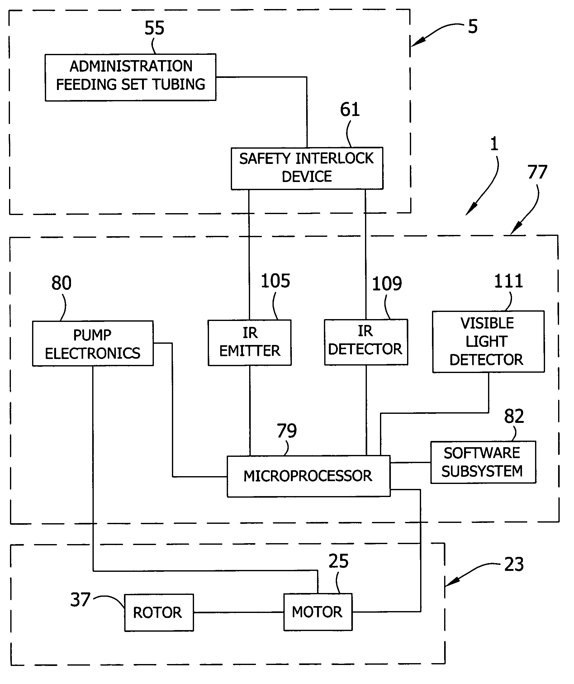
[0042]In the first embodiment, the pump includes an infrared (“IR”) emitter 105 (broadly, “a source of electromagnetic radiation”) housed in the second lower recess 47. Referring to FIGS. 5 and 6, the IR emitter 105 is operatively connected to the controller 77 for emitting an electromagnetic signal having a (“first”) wavelength in the infrared range in a direction for striking the safety interlock device 61 of the feeding set 5. In the illustrated embodiment, the source of electromagnetic radiation is an infrared (IR) emitter 105 but it is understood that other types of sources of electromagnetic radiation may be used without departing from the scope of this invention. An infrared (“IR”) detector 109 located in the second lower recess 47 is operatively connected to the controller 77 for receiving the infrared signal from the IR emitter 105 and providing an indication to the controller that the feeding set 5 is properly positioned in the pump 1. In the illustrated embodiment, the IR...

third embodiment

[0049]FIG. 7A shows a seat 159 and a safety interlock device 161 of the present invention. In this embodiment, the safety interlock device 161 includes a reflector 165 on the external radial surface of an electromagnetic radiation propagation affecting member 167. The reflector 165 may be a layer of reflective tape or a layer of polished metal affixed to the remainder of the electromagnetic radiation propagation affecting member 167. In the embodiment of FIG. 7A, the IR emitter 169, the IR detector 171, and the visible light detector 173 are arranged in an alcove 175 in a radially facing surface 177 of housing 179 in a manner such that the three devices are generally vertically aligned and parallel to each other. It is understood the IR emitter 169, IR detector 171, and visible light detector 173 may be otherwise arranged. When the safety interlock device 161 is received in the seat 159, the infrared radiation emitted from the IR emitter 169 is reflected off the reflector 165 and tr...

fourth embodiment

[0050]FIG. 8 shows a seat 189 and safety interlock device 191 of the present invention. As in the prior embodiments, the safety interlock device 191 can be removably positioned on the seat 191 and thereby releasably attached to the pump by the user or caregiver. In this embodiment, the safety interlock device 191 includes a light pipe 195 (“an electromagnetic radiation propagation affecting member”) received in the seat 189 of the housing 199 when the feeding set 201 is loaded on the pump. The light pipe 195 includes an outer annular portion 205, an angled annular wall 207, and a central portion 209 between the angled wall and the upper portion 211 that receives a tube 213 of the feeding set 201. As shown in FIG. 8, the IR emitter 217 and IR detector 219 are both housed below a bottom wall 221 of the seat 189. The IR emitter 217 directs infrared radiation upward to the outer annular portion 205 of the light pipe 195 that is reflected by the angled annular wall 207 through the centra...


PUM


Abstract

A pump set for use with a pump to deliver a supply of liquid to a patient. The feeding set has a conduit for the nutrient liquid and a safety interlock device associated with the conduit. The pumping apparatus has a pumping device and a control system for controlling operation of the pump. An electromagnetic radiation source is operatively connected to the control system of the pump for emitting an electromagnetic radiation signal in a direction for striking the safety interlock device of the feeding set. The safety interlock device is adapted to affect the direction of the electromagnetic radiation. An electromagnetic radiation detector is operatively connected to the control system for receiving the electromagnetic radiation signal when the direction is affected by the safety interlock device, and providing an indication to the control system that the feeding set conduit is properly positioned in the feeding pump.

Description

BACKGROUND[0001]This invention relates generally to pump sets to deliver fluids to patients by way of a flow control apparatus, and more particularly to a pump set having a safety interlock device for determining secure loading of the pump set on the pump.[0002]Administering fluids containing medicine or nutrition to a patient is well known in the art. Fluids can be delivered to patients by gravity flow, but often are delivered to the patient by a pump set loaded on a flow control apparatus, such as a peristaltic pump, which delivers fluid to the patient at a controlled rate of delivery. A peristaltic pump usually comprises a housing that includes a rotor or the like operatively engaged to at least one motor through a gearbox. The rotor drives fluid through the tubing of the pump set by the peristaltic action effected by rotation of the rotor by the motor. The motor is operatively connected to a rotatable shaft that drives the rotor, which in turn progressively compresses the tubing...

Claims


Application Information

Patent Timeline
Patent Type & Authority Patents(United States)
IPC IPC(8): A61M5/00A61F5/44A61M1/00A61M31/00
CPCA61M5/14212A61M5/16831A61M5/14232A61M2205/14A61M2205/3313A61M5/168A61M5/142A61M31/00
Inventor WIESNER, JOEL D.KNAUPER, CHRISTOPHER A.HARR, JAMES M.HANLON, JAMES G.HUDSON, JOSEPH A.SISK, RICKY A.GAINES, ROBERT B.MEIER, KEVIN C.
Owner KPR U S LLC
Why Eureka
Try Eureka